10.1 - Universal Certification Comparison Tables
Module: Universal Review and Mock Examinations
Covers: Cumulative comparison of Core, Type I, Type II, and Type III material from Modules 1–9
Regulatory verification date: August 14, 2026
Primary current authority: 40 CFR Part 82, Subpart F and current U.S. EPA Section 608 guidance
Course role: Consolidates the most important similarities, differences, controlling conditions, procedures, and examination traps before the Universal mock examinations
Learning Objectives
After completing this section, a student should be able to:
- Compare Type I, Type II, and Type III appliance scope without relying on equipment appearance alone.
- Select the correct certification category from the small-appliance definition and refrigerant pressure classification.
- Compare the recovery and evacuation requirements that apply to Type I, Type II, and Type III appliances.
- Distinguish small-appliance recovery percentages from the Table 1 evacuation requirements used for larger appliances.
- Apply the current definitions of major maintenance, service, or repair and the limited non-major opening provisions.
- Distinguish Section 608 leak-repair applicability from appliance certification type.
- Compare charging procedures, especially the special vapor-first charging concern for deeply evacuated low-pressure chillers.
- Identify the primary safety hazards and common examination traps associated with each certification type.
- Use a single decision process to move from appliance identification to the correct Type I, Type II, or Type III rule.
- Recognize which facts are universal service principles and which depend on appliance type, pressure category, charge size, equipment date, or repair condition.
Introduction
Universal certification preparation requires more than memorizing three separate lists of facts. The examination frequently tests whether the candidate can identify which set of rules applies when several answer choices contain technically reasonable statements.
The most important first step is therefore classification:
WHAT APPLIANCE IS THIS?
→ Type I?
→ Type II?
→ Type III?
Only after the appliance is classified should the student select:
- The recovery method.
- The recovery or evacuation endpoint.
- The applicable repair condition.
- The charging approach.
- The relevant safety concern.
The tables in this section consolidate material already developed in Modules 1–9. They are designed for cumulative Universal review and do not replace the detailed explanations in the earlier modules.
1. Core, Type I, Type II, Type III, and Universal
| Examination Area | Main Role |
|---|---|
| Core | Common environmental, regulatory, refrigeration, recovery, evacuation, cylinder, and safety knowledge |
| Type I | Small appliances |
| Type II | Medium-, high-, and very-high-pressure appliances, except specified exclusions |
| Type III | Low-pressure appliances |
| Universal | Combined certification covering Types I, II, and III after the required examination sections are passed |
Universal Relationship
CORE
+
TYPE I
+
TYPE II
+
TYPE III
=
UNIVERSAL
Exam trap: Universal is not a fourth appliance category. It is the combined certification covering the appliance categories addressed by Types I, II, and III.
2. Master Type I, Type II, and Type III Comparison
| Comparison Item | Type I | Type II | Type III |
|---|---|---|---|
| Primary appliance category | Small appliances | Medium-, high-, and very-high-pressure appliances | Low-pressure appliances |
| Classification basis | Complete small-appliance definition | Refrigerant pressure category after Type I and MVAC boundaries are excluded | Refrigerant pressure category |
| Typical examples | Household refrigerator, window A/C, dehumidifier, qualifying PTAC/PTHP | Split A/C, heat pump, rooftop unit, walk-in, supermarket rack | Low-pressure centrifugal or absorption chiller |
| Normal pressure behavior | Depends on refrigerant and appliance | Normally includes positive-pressure systems with medium to very high saturation pressure | Often operates below atmospheric pressure in portions of the system |
| Primary recovery emphasis | Small-appliance percentage or 4 in. Hg vacuum requirement | Certified recovery equipment; liquid recovery where practical, then vapor; Table 1 endpoint | Liquid first, then substantial vapor recovery; freeze prevention; Table 1 endpoint |
| Major-repair distinction | Not the controlling basis for the small-appliance percentage requirement | Important for Table 1 versus qualifying non-major opening provisions | Important for Table 1 versus qualifying non-major opening provisions |
| Special charging concern | Follow refrigerant and manufacturer procedure | Follow refrigerant and manufacturer procedure | Deeply evacuated chiller: vapor first, liquid later after pressure and saturation temperature are safely raised |
| Characteristic hazard | Access fitting leaks, electrical hazards, frostbite, pressure | High pressure, compressor/electrical hazards, nitrogen testing, very-high-pressure systems | Water freezing, air/moisture infiltration, low-pressure recovery, relief protection, machinery-room and water-side hazards |
| Classic exam trap | “5 lb or less” by itself does not make an appliance Type I | 15 lb, 50 lb, and 200 lb refer to different rules | “Low pressure” does not mean every point is always under vacuum |
3. Appliance Classification Comparison
Type I Small-Appliance Test
A small appliance must satisfy all four conditions:
FULLY MANUFACTURED AT A FACTORY
+
FACTORY CHARGED
+
HERMETICALLY SEALED AT A FACTORY
+
5 lb OR LESS OF REFRIGERANT
| Question | Type I Requirement |
|---|---|
| Fully manufactured at a factory? | Yes |
| Charged at a factory? | Yes |
| Hermetically sealed at a factory? | Yes |
| Refrigerant charge 5 lb or less? | Yes |
Exam trap: A field-connected split system containing 4 lb of refrigerant is not Type I merely because the charge is below 5 lb.
Pressure Categories Used for Type II and Type III
| Pressure Category | Current Definition at | Section 608 Type |
|---|---|---|
| Low pressure | Liquid-phase saturation pressure below 45 psia | Type III |
| Medium pressure | Liquid-phase saturation pressure 45 to 170 psia | Type II |
| High pressure | Liquid-phase saturation pressure 170 to 355 psia | Type II |
| Very high pressure | Critical temperature below or liquid-phase saturation pressure above 355 psia at | Type II |
Fast Classification Sequence
1. MVAC?
   → Section 609 service framework

2. MVAC-like?
   → Type II or applicable Section 609 pathway

3. Small appliance?
   → Type I

4. Low-pressure appliance?
   → Type III

5. Medium-, high-, or very-high-pressure appliance?
   → Type II
Representative Equipment
| Equipment | Most Likely Classification | Key Reason |
|---|---|---|
| Factory-sealed household refrigerator | Type I | Listed small-appliance example when the complete definition is met |
| Window air conditioner | Type I | Common factory-sealed small appliance |
| Packaged terminal air conditioner meeting the definition | Type I | Factory-manufactured, charged, sealed, 5 lb or less |
| Field-connected residential split A/C | Type II | Not a factory-sealed small appliance |
| Field-connected mini-split | Type II | Field refrigerant connection prevents Type I classification |
| Residential split heat pump | Type II | Common field-connected Type II appliance |
| Rooftop package unit | Type II | Common Type II appliance |
| Walk-in cooler or freezer | Type II | Field-installed refrigeration system |
| Supermarket compressor rack | Type II | Common commercial refrigeration application |
| Low-pressure centrifugal chiller | Type III | Low-pressure refrigerant category |
| Low-pressure absorption chiller | Type III | Low-pressure appliance |
| Passenger-car air conditioner serviced for consideration | Section 609 | MVAC rather than ordinary stationary Section 608 service |
| Qualifying off-road MVAC-like appliance | Type II or Section 609 | Special certification pathway |
| Refrigerated-cargo system | Section 608 classification | Cargo cooling is not ordinary passenger-compartment MVAC cooling |
4. Recovery Equipment and Method Comparison
Recovery Equipment Categories
| Item | Type I | Type II | Type III |
|---|---|---|---|
| Self-contained recovery equipment | Permitted | Common | Common |
| System-dependent recovery equipment | Permitted; small-appliance charge is within the general 15-lb limit | Not permitted above 15 lb unless permanently attached as a pump-out unit | Not permitted above 15 lb unless permanently attached as a pump-out unit |
| Certified recovery equipment | Required as applicable | Required | Required |
| Low-loss connections | Use to minimize refrigerant release | Use to minimize refrigerant release | Use to minimize refrigerant release |
| Mixed refrigerants | Keep separate | Keep separate | Keep separate |
Typical Recovery Approach
| Type | High-Priority Recovery Logic |
|---|---|
| Type I, operating compressor with system-dependent recovery | Operate the appliance compressor and recover from the high side when the equipment configuration permits |
| Type I, failed compressor with system-dependent recovery | Access both high and low sides when needed to speed and complete recovery; heat or other approved methods may help release trapped refrigerant |
| Type I, self-contained recovery | Recovery machine provides its own means of drawing refrigerant into an approved recovery cylinder |
| Type II | Recover accessible bulk liquid efficiently where practical, then recover the remaining vapor; use suitable access points and isolate receivers or components when the system design permits |
| Type III | Recover liquid first, then vapor; maintain required water management and recovery-machine condenser cooling to prevent freezing and excessive pressure |
Recovery-Speed Principles That Apply Across Types
Recovery generally becomes faster when:
- Hoses are shorter.
- Hoses have larger internal diameter.
- Unnecessary restrictions are removed.
- Useful high- and low-side access is provided.
- Appliance pressure is maintained safely by controlled warming where appropriate.
- Recovery-cylinder temperature and pressure are controlled safely.
- Bulk liquid is removed before the slower final vapor stage when the procedure permits.
Recovery becomes slower when:
- The appliance becomes very cold.
- Long, small-diameter hoses create pressure drop.
- Refrigerant remains dissolved in oil.
- Liquid refrigerant is trapped in isolated components.
- Noncondensables raise recovery-machine discharge pressure.
Exam trap: A vacuum pump is not a substitute for a refrigerant recovery machine simply because both can reduce pressure.
5. Type I Recovery Requirement
Small appliances use a recovery-percentage requirement or the four-inch-Hg vacuum alternative rather than the Type II/III Table 1 rows.
| Recovery Condition | Required Type I Result |
|---|---|
| Recovery/recycling equipment manufactured before November 15, 1993 | Recover 80% of the refrigerant |
| Equipment manufactured on or after November 15, 1993 and compressor is functional | Recover 90% |
| Equipment manufactured on or after November 15, 1993 and compressor is not functional | Recover 80% |
| Alternative | Evacuate the small appliance to 4 in. Hg vacuum |
Type I Memory Pattern
POST-1993 EQUIPMENT
+
COMPRESSOR WORKS
→ 90%
COMPRESSOR DOES NOT WORK
→ 80%
PRE-1993 RECOVERY EQUIPMENT
→ 80%
ALTERNATIVE
→ 4 in. Hg VACUUM
Exam trap: The date belongs to the recovery/recycling equipment, not the appliance.
6. Type II and Type III Required Evacuation Comparison
For appliances other than small appliances, MVACs, and MVAC-like appliances, the current Table 1 evacuation levels depend on:
- Pressure category.
- Full refrigerant charge for certain Type II rows.
- Whether the recovery/recycling equipment was manufactured or imported before or on/after November 15, 1993.
Current Table 1
| Appliance | Pre-Nov. 15, 1993 Recovery Equipment | On/After Nov. 15, 1993 Recovery Equipment |
|---|---|---|
| Very-high-pressure appliance | 0 in. Hg vacuum | 0 in. Hg vacuum |
| High-pressure appliance, less than 200 lb | 0 in. Hg vacuum | 0 in. Hg vacuum |
| High-pressure appliance, 200 lb or more | 4 in. Hg vacuum | 10 in. Hg vacuum |
| Medium-pressure appliance, less than 200 lb | 4 in. Hg vacuum | 10 in. Hg vacuum |
| Medium-pressure appliance, 200 lb or more | 4 in. Hg vacuum | 15 in. Hg vacuum |
| Low-pressure appliance | 25 mm Hg absolute | 25 mm Hg absolute |
High-Priority Type II Patterns
For post-1993 recovery equipment:
VERY HIGH PRESSURE
→ 0 in. Hg vacuum
HIGH PRESSURE <200 lb
→ 0 in. Hg vacuum
HIGH PRESSURE ≥200 lb
→ 10 in. Hg vacuum
MEDIUM PRESSURE <200 lb
→ 10 in. Hg vacuum
MEDIUM PRESSURE ≥200 lb
→ 15 in. Hg vacuum
High-Priority Type III Pattern
LOW PRESSURE
→ 25 mm Hg ABSOLUTE
The Type III value is:
- The same for pre- and post-November 15, 1993 recovery equipment.
- Not changed by the 200-lb boundary.
Exam trap:
25 mm Hg absoluteis not the same type of vacuum expression as25 in. Hg vacuum.
7. Major Repair and Special Opening Conditions
Current Major Maintenance, Service, or Repair Definition
Work is major when it involves removal of any of the following:
- Compressor.
- Condenser.
- Evaporator.
- Auxiliary heat-exchange coil.
Work is also major when it involves uncovering:
AN OPENING >4 in² OF FLOW AREA
FOR
>15 MINUTES
Comparison by Type
| Topic | Type I | Type II | Type III |
|---|---|---|---|
| Major-repair definition exists | Yes | Yes | Yes |
| Main recovery rule controlled by major/non-major distinction? | No. Small appliances use the Type I percentage / 4-in.-Hg recovery rule | Yes. Major work normally requires the applicable Table 1 endpoint | Yes. Major work normally requires the low-pressure Table 1 endpoint |
| Qualifying non-major opening provision | Small-appliance recovery rule remains the controlling recovery framework | Appliance may be evacuated to no higher than 0 psig before opening when all current conditions are satisfied | Appliance may be pressurized to no higher than 0 psig before opening when all current conditions are satisfied |
| Oil-change special provision | Follow applicable small-appliance procedure | No higher than 5 psig under the current oil-change provision | No higher than 5 psig under the current oil-change provision |
| Leak prevents normal endpoint | Apply the applicable small-appliance recovery requirement and current service practice | Isolate when possible; non-leaking portions to Table 1, leaking portions to lowest attainable level not above 0 psig | Same isolation principle; leaking portions to lowest attainable level not above 0 psig |
Major-Repair Decision
REMOVE COMPRESSOR / CONDENSER / EVAPORATOR /
AUXILIARY HEAT-EXCHANGE COIL?
→ YES
→ MAJOR
If no:
OPENING >4 in²
AND
OPEN >15 min?
→ YES
→ MAJOR
Otherwise:
POTENTIALLY NON-MAJOR
→ CHECK ALL § 82.156 CONDITIONS
Exam trap: A filter-drier is not one of the four named major components. Whether the work is major can still depend on the actual opening size and duration.
8. Leak-Repair Applicability Comparison
The current Section 608 leak-repair program is not determined by Type I, Type II, or Type III certification alone.
Current Section 608 leak-repair requirements apply when an appliance:
- Has a full charge of 50 lb or more.
- Contains an ozone-depleting refrigerant subject to the Section 608 leak-repair rule.
- Exceeds the applicable leak-rate trigger.
Current Section 608 Trigger Rates
| End-Use Category | Trigger Rate Over a 12-Month Period |
|---|---|
| Industrial process refrigeration | 30% |
| Commercial refrigeration | 20% |
| Comfort cooling | 10% |
| All other appliances | 10% |
Type Comparison
| Type | Section 608 Leak-Repair Program Applicability |
|---|---|
| Type I | Ordinarily not applicable because a small appliance contains no more than 5 lb, far below the 50-lb full-charge threshold |
| Type II | May apply when the appliance contains 50 lb or more of an applicable ozone-depleting refrigerant and exceeds the end-use trigger rate |
| Type III | May apply under the same current conditions; a low-pressure chiller is not exempt merely because it is Type III |
Critical Distinction
TYPE II / TYPE III
≠
LEAK-RATE CATEGORY
The trigger rate is determined by end use, such as:
- Comfort cooling.
- Commercial refrigeration.
- Industrial process refrigeration.
- Other appliance category.
It is not determined by whether the technician needs Type II or Type III certification.
Current-versus-historical warning: Older study guides may show historical 15% and 35% values. Those values are not the current Section 608 trigger-rate table.
Separate regulatory framework: Current federal HFC leak-repair requirements under the AIM Act are separate from the traditional Section 608 ozone-depleting-refrigerant leak-repair table. See Section 8.5 for the current distinction.
9. Charging Procedure Comparison
Charging procedure depends on:
- Refrigerant.
- Appliance design.
- Manufacturer instructions.
- System pressure.
- Whether the appliance is under deep vacuum.
- Whether the refrigerant is a blend.
It should not be selected from certification type alone.
Type Comparison
| Type | High-Priority Charging Reminder |
|---|---|
| Type I | Follow appliance and refrigerant instructions. Zeotropic and near-azeotropic blends are charged from the source as liquid to avoid fractionation. |
| Type II | Follow manufacturer and refrigerant procedures. Blends that require liquid charging must be handled as liquid from the source. Avoid assuming one charging method fits every Type II system. |
| Type III | Use the low-point / evaporator charging connection as applicable. When the chiller is deeply evacuated, introduce vapor first to raise pressure and saturation temperature before introducing liquid. Use manufacturer instructions to determine the safe transition to liquid charging. |
Type III Freeze-Prevention Logic
DEEP VACUUM
+
LIQUID REFRIGERANT ADDED TOO EARLY
→ RAPID BOILING
→ VERY LOW SATURATION TEMPERATURE
→ WATER-FREEZING RISK
Therefore:
DEEPLY EVACUATED LOW-PRESSURE CHILLER
→ VAPOR FIRST
→ RAISE PRESSURE / SATURATION TEMPERATURE
→ LIQUID LATER
Exam trap: “Charge blends as liquid” and “charge a deeply evacuated low-pressure chiller with vapor first” answer different questions. A blend may need to leave the source cylinder as liquid while the low-pressure charging procedure still requires controlled vapor introduction into the deeply evacuated appliance.
10. Type III Purge, Leak-Test, and Freeze-Prevention Distinctions
These features sharply distinguish Type III from Type II.
| Type III Condition | Correct Review Point |
|---|---|
| Appliance operates below atmospheric pressure | Air and moisture can leak into the appliance |
| Noncondensables accumulate | Purge unit removes air and other noncondensables while minimizing refrigerant loss |
| Frequent purge operation | Possible indication of air infiltration |
| Excess moisture collected by purge system | Possible tube leakage |
| Leak test of low-pressure appliance | Controlled heat is preferred where applicable; nitrogen is used only under the applicable conditions |
| Traditional Type III exam leak-test maximum | 10 psig |
| Recovery | Liquid first, vapor second |
| Water in evaporator/condenser tubes during deep recovery | Circulate or remove water as required to prevent freezing |
| Tube leak suspected | Drain affected water sides before recovery under the Type III procedure |
| Low-pressure recovery-machine high-pressure cutout exam value | 10 psig |
| Low-pressure recovery-vessel rupture-disc exam value | 15 psig |
| Oil removal exam value | Heat oil to 130°F before removal to reduce dissolved refrigerant |
| Current oil-change opening provision | No higher than 5 psig |
| Final normal Table 1 evacuation level | 25 mm Hg absolute |
Do not combine unrelated values: The 10-psig Type III leak-test value, 15-psig recovery-vessel rupture-disc value, 5-psig oil-change provision, and 25-mm-Hg-absolute evacuation endpoint apply to different situations.
11. Primary Safety Hazard Comparison
Safety Rules Common to All Types
All Section 608 work requires attention to:
- Eye and skin protection.
- Frostbite risk.
- Oxygen displacement and asphyxiation.
- Refrigerant-specific toxicity and flammability.
- Electrical hazards.
- Cylinder condition and fill limits.
- Heat exposure of cylinders.
- Ignition sources.
- Proper ventilation.
- Manufacturer instructions.
- Recovery-machine operating limits.
Never use oxygen or compressed air as a substitute for dry nitrogen in refrigerant-system pressure testing.
Type-Specific Emphasis
| Type | Primary Safety Emphasis |
|---|---|
| Type I | Safe installation and removal of temporary access fittings; small sealed-system pressure; frostbite; electrical hazards; avoiding leaks from piercing valves and service stubs |
| Type II | Medium/high/very-high pressure; regulator and relief protection during nitrogen testing; high discharge pressure; compressor service; pressure relief; electrical hazards; refrigerant migration and crankcase conditions |
| Type III | Water freezing during deep recovery; low-pressure pressurization limits; rupture-disc and relief protection; machinery-room monitoring and ventilation; air/moisture infiltration; water-side pressure and stored energy |
High-Priority Type II Safety Traps
- Never energize a reciprocating compressor with its discharge service valve closed.
- Do not energize a hermetic compressor motor under a deep vacuum when the procedure creates a risk of motor-winding damage.
- Noncondensables can raise discharge pressure.
- Use a regulator and downstream relief protection for nitrogen pressure testing.
High-Priority Type III Safety Traps
- Low-pressure does not mean no pressure hazard.
- A rupture disc is a non-reclosing emergency relief device.
- A refrigerant monitor measures refrigerant concentration; an oxygen monitor measures oxygen concentration.
- A machinery room is not automatically an OSHA confined space.
- A stopped water pump does not prove that water-side pressure is zero.
- Control hazardous energy and verify pressure before opening water-side components.
12. Common Universal Numerical Traps
| Number | What It Means | What It Does Not Mean |
|---|---|---|
| 5 lb | Maximum refrigerant charge in the small-appliance definition | Not the Type II system-dependent recovery limit |
| 15 lb | General maximum full charge for use of system-dependent recovery equipment unless permanently attached as a pump-out unit | Not the Type II evacuation-table boundary |
| 50 lb | Full-charge threshold for the current Section 608 ODS leak-repair program | Not the small-appliance limit |
| 200 lb | Charge boundary that changes certain Type II Table 1 rows | Not a leak-repair threshold |
| 80% | Type I recovery requirement under specified conditions | Not a cylinder fill rule |
| 90% | Type I recovery requirement with post-1993 equipment and functional compressor | Not a Universal passing score |
| 4 in. Hg vacuum | Type I alternative recovery endpoint; also appears in some pre-1993 Type II Table 1 rows | Not 4 psig |
| 25 mm Hg absolute | Type III normal Table 1 evacuation endpoint | Not 25 in. Hg vacuum |
| 0 psig | Atmospheric gauge pressure and a special opening endpoint in certain current service provisions | Not a perfect vacuum |
| 5 psig | Current special oil-change pressure limit | Not the Type I charge limit |
| 10 psig | Traditional Type III leak-test maximum and a separate recovery-unit cutout exam value | Not the Type III final evacuation endpoint |
| 15 psig | Traditional low-pressure recovery-vessel rupture-disc exam value | Not a universal chiller rupture-disc setting |
| 130°F | Type III oil-heating exam value before oil removal | Not a refrigerant cylinder heating target |
13. Common Exam Traps by Certification Type
Type I
- Treating every appliance with 5 lb or less as Type I.
- Using the appliance manufacture date instead of the recovery-equipment date.
- Selecting 90% when the compressor is not functional.
- Forgetting the 4-in.-Hg-vacuum alternative.
- Confusing a temporary piercing valve with a desirable permanent service fitting.
- Assuming disposal means refrigerant may be vented.
- Confusing system-dependent and self-contained recovery equipment.
Type II
- Forgetting that current Type II scope includes medium pressure.
- Confusing the 15-lb system-dependent-equipment limit with the 200-lb Table 1 boundary.
- Using the appliance manufacture date instead of the recovery-equipment manufacture/import date.
- Applying one evacuation level to every Type II appliance.
- Treating a compressor, condenser, evaporator, or auxiliary heat-exchanger removal as non-major.
- Applying old 15%/35% leak-rate values as current law.
- Treating every commercial refrigeration appliance as Type II without first checking the small-appliance definition.
- Assuming every chiller is Type III.
- Treating high head pressure as proof of overcharge when noncondensables or condenser problems may also be involved.
Type III
- Assuming every point in a low-pressure appliance is always below atmospheric pressure.
- Forgetting that air and moisture enter when local appliance pressure is below atmospheric pressure.
- Treating the purge unit as a refrigerant recovery machine for the entire chiller.
- Forgetting liquid-first then vapor recovery.
- Failing to circulate or remove water to prevent freezing during deep recovery.
- Adding liquid refrigerant directly to a deeply evacuated chiller before pressure and saturation temperature are safely raised.
- Confusing 25 mm Hg absolute with inches of Hg vacuum.
- Mixing the 10-psig leak-test limit, 15-psig recovery-vessel rupture-disc value, 5-psig oil-change provision, and 25-mm-Hg-absolute evacuation endpoint.
- Treating a refrigerant monitor and an oxygen monitor as the same instrument.
- Assuming low operating pressure means low mechanical or machinery-room hazard.
14. Universal Decision Tables
Certification Decision
| If the appliance is… | Select… |
|---|---|
| Fully factory manufactured, charged, hermetically sealed, and 5 lb or less | Type I |
| Medium-, high-, or very-high-pressure and not excluded | Type II |
| Low pressure | Type III |
| Across all three Section 608 categories | Universal |
Recovery / Evacuation Decision
| Question | Decision Direction |
|---|---|
| Small appliance? | Use Type I 80% / 90% / 4-in.-Hg rule |
| Not a small appliance? | Use current Table 1 unless a listed exception applies |
| Type II? | Identify pressure category, charge boundary where applicable, and recovery-equipment date |
| Type III? | Normal endpoint is 25 mm Hg absolute |
| Qualifying non-major opening? | Check the current 0-psig special provision |
| Oil change? | Check the separate no-higher-than-5-psig provision |
| Leak prevents Table 1? | Isolate where possible; non-leaking portion to Table 1, leaking portion to lowest attainable level not above 0 psig |
Leak-Repair Decision
FULL CHARGE ≥50 lb?
        |
        NO
        ↓
SECTION 608 ODS LEAK-REPAIR PROGRAM NOT TRIGGERED
        |
       YES
        ↓
APPLICABLE OZONE-DEPLETING REFRIGERANT?
        |
       YES
        ↓
CALCULATE / DETERMINE LEAK RATE
        |
        ↓
COMPARE WITH END-USE TRIGGER
Do not select a trigger rate from Type I, Type II, or Type III alone.
15. Universal Master Memory Map
TYPE I
→ SMALL APPLIANCE
→ FACTORY MADE + FACTORY CHARGED + FACTORY SEALED + ≤5 lb
→ 80% / 90% OR 4 in. Hg VACUUM
TYPE II
→ MEDIUM / HIGH / VERY HIGH PRESSURE
→ TABLE 1 DEPENDS ON PRESSURE CATEGORY
→ SOME ROWS ALSO DEPEND ON 200-lb BOUNDARY
→ RECOVERY-EQUIPMENT DATE MATTERS
TYPE III
→ LOW PRESSURE
→ AIR + MOISTURE CAN LEAK IN
→ PURGE UNIT
→ LIQUID FIRST, VAPOR SECOND
→ PREVENT WATER FREEZING
→ VAPOR-FIRST INITIAL CHARGING FROM DEEP VACUUM
→ 25 mm Hg ABSOLUTE
ALL TYPES
→ DO NOT VENT
→ IDENTIFY REFRIGERANT
→ DO NOT MIX REFRIGERANTS
→ USE APPROPRIATE CERTIFIED RECOVERY EQUIPMENT
→ USE LOW-LOSS PRACTICES
→ PROTECT RECOVERY CYLINDER FROM OVERFILL / HEAT
→ FOLLOW SAFETY + MANUFACTURER INSTRUCTIONS
Figures and Diagrams
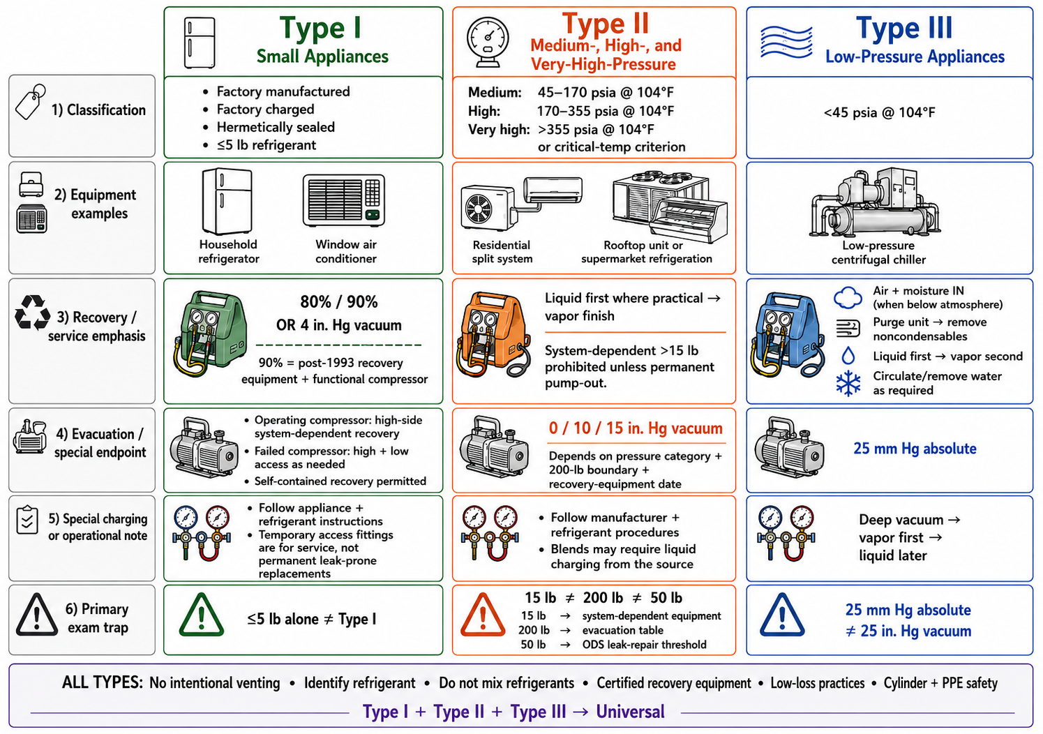
Figure 10.1.1 – Universal master comparison of Type I, Type II, and Type III appliance scope and service requirements.
AI-generated instructional figure: It may contain visual inaccuracies. Use the accompanying lesson text and cited authoritative sources to verify technical and regulatory details.
EPA 608 Exam Focus
The First Question to Ask
When a Universal question describes an appliance, first ask:
WHICH TYPE?
Do not begin by selecting a recovery value.
A correct decision sequence is:
CLASSIFY APPLIANCE
→ IDENTIFY CONTROLLING CONDITION
→ SELECT RULE
→ CHECK UNITS
→ CHECK EXCEPTION
Controlling Conditions That Commonly Change the Answer
- Complete small-appliance definition.
- Refrigerant pressure category.
- Refrigerant charge.
- Recovery-equipment manufacture/import date.
- Functional or nonfunctional compressor.
- System-dependent or self-contained recovery equipment.
- Major or non-major repair.
- Leak preventing the normal endpoint.
- Oil change.
- Service versus disposal.
- Appliance end use.
- Ozone-depleting refrigerant versus substitute.
- Deep vacuum versus positive pressure.
- Liquid versus vapor refrigerant.
- Pure refrigerant versus blend.
High-Priority Universal Distinctions
| Do Not Confuse | Correct Distinction |
|---|---|
| 5 lb and 15 lb | Small-appliance definition versus system-dependent recovery-equipment limit |
| 15 lb and 200 lb | Recovery-equipment limitation versus Type II evacuation-table boundary |
| 50 lb and 200 lb | Section 608 ODS leak-repair threshold versus evacuation-table boundary |
| 80% / 90% and 80% cylinder fill | Small-appliance recovery requirement versus recovery-cylinder fill rule |
| 4 in. Hg vacuum and 4 psig | Vacuum level versus positive gauge pressure |
| 25 mm Hg absolute and 25 in. Hg vacuum | Different units and reference systems |
| 0 psig and perfect vacuum | Atmospheric gauge pressure versus zero absolute pressure |
| Type II and commercial refrigeration | Many commercial systems are Type II, but small-appliance definition and pressure category still control |
| Type III and “chiller” | Not every chiller is low pressure |
| Leak-repair category and certification type | Leak trigger is based on current applicability and end use, not Type II versus Type III |
| Blend liquid charging and Type III vapor-first charging | Refrigerant source handling versus safe initial introduction into a deeply evacuated low-pressure appliance |
| Recovery and evacuation | Refrigerant removal for regulatory recovery endpoint versus dehydration/deep vacuum after recovery |
Common Mistakes and Confusing Points
Mistake 1: Choosing a Type From Equipment Size
Large equipment is not automatically Type III, and small-looking equipment is not automatically Type I.
Mistake 2: Memorizing a Number Without Its Condition
Every high-priority number should be stored with its controlling condition.
Bad memory:
200 lb
Better memory:
200 lb
→ changes certain Type II Table 1 rows
Mistake 3: Treating Recovery and Dehydration as the Same Process
Meeting the required refrigerant-recovery endpoint is not the same as completing a deep dehydration vacuum after the system is opened and repaired.
Mistake 4: Applying Type II Logic to Type III
A Type III appliance may pull air and moisture inward during normal operation because its internal pressure can be below atmospheric pressure.
Mistake 5: Applying Type III Logic to Every Chiller
A chiller must be classified by refrigerant pressure category.
Mistake 6: Applying Historical Leak Rates as Current
The old 15% and 35% study-guide values must not replace the current Section 608 10% / 20% / 30% trigger structure.
Mistake 7: Confusing the Three Type II Charge Numbers
Remember:
15 lb → system-dependent recovery equipment
50 lb → current Section 608 ODS leak-repair applicability
200 lb → certain Type II evacuation-table rows
Mistake 8: Ignoring Units
The Type III endpoint is:
25 mm Hg ABSOLUTE
not:
25 in. Hg vacuum
Mistake 9: Treating “Low Pressure” as “No Pressure”
Low-pressure chillers can be pressurized for specific procedures and contain relief devices because damaging positive pressure is possible.
Mistake 10: Forgetting the Common Rules
Type-specific knowledge does not replace Core requirements. Venting, refrigerant identification, recovery-equipment use, cylinder safety, PPE, and safe service practices remain important across the Universal examination.
Section Summary
Universal certification review is fundamentally a classification-and-condition problem.
Type I
SMALL APPLIANCE
→ FACTORY MANUFACTURED
→ FACTORY CHARGED
→ HERMETICALLY SEALED
→ ≤5 lb
Recovery:
80% / 90%
OR
4 in. Hg vacuum
Type II
MEDIUM / HIGH / VERY HIGH PRESSURE
→ TYPE II
Recovery and evacuation depend on:
PRESSURE CATEGORY
+
CHARGE WHERE APPLICABLE
+
RECOVERY-EQUIPMENT DATE
+
REPAIR CONDITION
Type III
LOW PRESSURE
→ TYPE III
Remember:
AIR + MOISTURE IN
PURGE UNIT
LIQUID FIRST → VAPOR SECOND
FREEZE PREVENTION
VAPOR FIRST WHEN CHARGING FROM DEEP VACUUM
25 mm Hg ABSOLUTE
Universal
CORE + TYPE I + TYPE II + TYPE III
→ UNIVERSAL
The next section consolidates the high-priority numbers and thresholds that must be recalled quickly during Universal practice and the official examination.
References
Current Regulatory and EPA Sources
-
U.S. Environmental Protection Agency, Section 608 Technician Certification Requirements, verified August 14, 2026.
-
U.S. Environmental Protection Agency, Section 608 Technician Certification, verified August 14, 2026.
-
U.S. Environmental Protection Agency, Required Level of Evacuation of Appliances, verified August 14, 2026.
-
U.S. Environmental Protection Agency, Stationary Refrigeration Service Practice Requirements, verified August 14, 2026.
-
U.S. Environmental Protection Agency, Refrigerant Recovery and Recycling Equipment Certification, verified August 14, 2026.
-
U.S. Environmental Protection Agency, Stationary Refrigeration Leak Repair Requirements, verified August 14, 2026.
-
U.S. Environmental Protection Agency, Definitions of Section 608 Terms, verified August 14, 2026.
-
U.S. Environmental Protection Agency, Stationary Refrigeration Safe Disposal Requirements, verified August 14, 2026.
-
Electronic Code of Federal Regulations, 40 CFR § 82.152 - Definitions, verified August 14, 2026.
-
Electronic Code of Federal Regulations, 40 CFR § 82.156 - Proper Evacuation of Refrigerant From Appliances, verified August 14, 2026.
-
Electronic Code of Federal Regulations, 40 CFR § 82.157 - Appliance Maintenance and Leak Repair, verified August 14, 2026.