7.6 - Recovery with a Failed Compressor
Module: Type I Small Appliances
Regulatory and exam-topic verification date: August 11, 2026
Primary verification basis: Current U.S. EPA Section 608 Type I test topics and current 40 CFR Part 82, Subpart F
Course role: Explains how Type I refrigerant recovery changes when the small-appliance compressor is inoperative, including the need for both high- and low-side access, methods used to free trapped refrigerant, and the special system-dependent arrangement that may use a vacuum pump with a nonpressurized recovery container
Learning Objectives
After completing this section, a student should be able to:
- Explain why recovery from a small appliance becomes more difficult when the appliance compressor is not operating.
- Explain why a failed-compressor system-dependent recovery procedure requires access to both the high side and the low side.
- Identify appropriate high-side and low-side access locations from the actual refrigeration circuit rather than from hose color alone.
- Explain how refrigerant can remain trapped in the compressor shell, oil, evaporator, condenser, and other portions of the circuit.
- Explain why controlled heat can help trapped liquid refrigerant vaporize and move toward the recovery path.
- Explain the Type I exam concept of heating and sharply striking or tapping the compressor to help release trapped refrigerant.
- Explain how an appliance defrost heater, when present and when its use is permitted, can help vaporize refrigerant trapped in a cold evaporator.
- Describe the special Type I system-dependent recovery example in which a vacuum pump is used with a nonpressurized recovery container.
- Distinguish that special arrangement from both a general deep-vacuum evacuation procedure and a self-contained recovery machine.
- Apply the current small-appliance recovery endpoint for a nonfunctioning compressor.
- Identify the major limitations of system-dependent recovery with a failed compressor.
- Recognize practices that can create refrigerant-release, fire, electrical, or equipment-damage hazards.
Introduction
Section 7.5 examined recovery when the small appliance has an operating compressor.
That situation allows the appliance compressor itself to help move refrigerant:
Evaporator / low side
→ appliance compressor
→ high side
→ recovery connection
A failed compressor changes the recovery problem.
If the compressor cannot operate:
appliance compressor
→ provides no active pumping force
The refrigerant circuit may still contain refrigerant on both sides of the compressor and metering restriction.
A typical small-appliance refrigeration circuit can be simplified as:
Compressor discharge
→ condenser
→ liquid line / filter-drier
→ capillary tube or metering restriction
→ evaporator
→ suction line
→ compressor inlet
When the compressor is operating, it can help create refrigerant movement through this circuit.
When the compressor has failed, that assistance is lost.
The capillary tube, compressor valves, oil, low temperatures, and liquid refrigerant trapped in different portions of the appliance can all slow the transfer of refrigerant toward a single recovery connection.
For this reason, EPA’s current Type I test topics specifically identify:
- Methods for recovering refrigerant from small appliances with inoperative compressors using a system-dependent or passive recovery device.
- The need to install both high- and low-side access valves when recovering from these appliances.
- Heating and sharply striking the compressor as an example of a technique used to help release refrigerant.
- Use of a vacuum pump with a nonpressurized recovery container as another Type I system-dependent recovery example.
These are Type I recovery concepts, not instructions to improvise a recovery device.
The actual recovery equipment must be certified for the intended application and used according to its manufacturer instructions unless those instructions conflict with the federal requirements.
Key Concepts
1. Failed Compressor Means No Compressor-Assisted Recovery
An operating appliance compressor can help move refrigerant from the low side toward the high side.
A failed compressor cannot provide that assistance.
Therefore:
Operating compressor
→ internal pumping assistance available
but:
Failed compressor
→ no internal compressor pumping assistance
This is the central reason the recovery connection strategy changes.
2. Both High-Side and Low-Side Access Are Needed
For the failed-compressor Type I system-dependent recovery concept:
HIGH SIDE
+
LOW SIDE
→ both connected to the recovery path
EPA specifically identifies the need to install both high- and low-side access valves when recovering refrigerant from a small appliance with an inoperative compressor.
This prevents the recovery setup from depending on refrigerant passing through:
- A failed compressor.
- Compressor reed or check valves.
- A restrictive capillary tube.
- Other internal restrictions.
A one-side-only connection can leave refrigerant isolated or slow to migrate from the opposite side.
3. Hose Color Does Not Define the System Side
The system connection must be identified from the refrigeration circuit.
For the standard manifold arrangement used in this course:
LOW-SIDE appliance access
→ BLUE hose
→ manifold LOW port
HIGH-SIDE appliance access
→ RED hose
→ manifold HIGH port
manifold CENTER / SERVICE port
→ recovery path
The important sequence is:
identify actual system side
→ install appropriate access
→ connect corresponding hose
Do not decide that a connection is high side merely because a red hose is attached to it.
4. Refrigerant Can Remain Trapped
A failed compressor does not mean the appliance is empty.
Refrigerant may remain:
- Dissolved in compressor oil.
- As liquid in the compressor shell.
- In the evaporator.
- In the condenser.
- In tubing low points.
- On either side of the capillary tube or other restriction.
During recovery, system pressure can fall enough that remaining liquid boils slowly.
Therefore:
initial pressure decrease
≠ all refrigerant removed
Additional time, controlled heat, access from both sides, or another manufacturer-approved technique may be needed to move the remaining refrigerant.
5. Heat Can Help Vaporize Trapped Refrigerant
Recovery normally becomes slower as the remaining refrigerant becomes colder and pressure falls.
Controlled heat can help by increasing the tendency of liquid refrigerant to vaporize.
Conceptually:
trapped liquid refrigerant
+ controlled heat
→ more vaporization
→ refrigerant becomes easier to move toward recovery path
The purpose is not to overheat the appliance.
Do not use:
- An open flame.
- A torch directed at a charged component.
- Uncontrolled high heat.
- A heat source prohibited by the appliance or recovery-equipment manufacturer.
The exact heating method depends on the appliance, refrigerant, service procedure, and equipment instructions.
6. Heating and Tapping the Compressor
EPA’s Type I test topics specifically include the example:
heat and sharply strike the compressor
for recovery from a small appliance with an inoperative compressor using a system-dependent recovery device.
For this course, interpret that exam phrase as a controlled service technique intended to help free refrigerant trapped in the compressor and compressor oil.
The concept is:
failed compressor
→ refrigerant may remain trapped in shell / oil
→ controlled heat promotes vaporization
→ controlled tapping or striking helps release trapped refrigerant
→ vapor can move toward recovery connection
This does not mean:
- Puncture the compressor.
- Crack the shell.
- Smash or deform the compressor.
- Strike electrical terminals.
- Create an ignition source.
- Use a torch on the compressor.
- Intentionally release refrigerant.
The objective is refrigerant movement, not mechanical destruction.
7. A Defrost Heater Can Assist at the Evaporator
Some small appliances have a defrost heater near the evaporator.
A cold evaporator can retain liquid refrigerant because low temperature corresponds to low saturation pressure.
If the appliance design and manufacturer procedure permit use of the defrost heater during recovery, controlled heat at the evaporator can help trapped refrigerant boil.
Conceptually:
cold evaporator
→ trapped liquid may remain
approved defrost-heater use
→ evaporator warms
→ liquid refrigerant vaporizes
→ vapor moves toward low-side recovery access
Do not assume every appliance has a defrost heater.
Do not bypass electrical safety devices or energize damaged equipment merely to obtain heat.
8. A Vacuum Pump Can Appear in a Special Type I Recovery Arrangement
A vacuum pump is normally taught as an:
evacuation / dehydration tool
rather than a general self-contained refrigerant recovery machine.
However, EPA’s current Type I test topics specifically include a failed-compressor system-dependent recovery example using:
vacuum pump
+
nonpressurized recovery container
This is a narrow Type I recovery context.
Therefore, both of the following statements are important:
Vacuum pump
≠ general substitute for a certified self-contained recovery machine
and:
Type I failed-compressor system-dependent method
→ may use a vacuum pump with a nonpressurized recovery container
→ when used as part of the appropriate certified recovery arrangement
The recovery setup must keep the refrigerant contained.
The vacuum pump must not be used as an excuse to discharge covered refrigerant to the atmosphere.
9. A Nonpressurized Recovery Container Is Not the Same as a Pressurized Recovery Cylinder
The special Type I example uses a:
nonpressurized recovery container
That term must not be casually replaced with:
pressurized recovery cylinder
The two concepts serve different recovery arrangements.
For the special system-dependent method:
- Use the container specified for the certified recovery-device arrangement.
- Follow the recovery-device and container manufacturer’s instructions.
- Do not improvise with an unapproved container.
- Do not intentionally pressurize a container that is intended for nonpressurized service.
- Do not discharge refrigerant from the container or vacuum-pump arrangement to atmosphere.
The next section, 7.7 - Self-Contained Recovery, covers the more familiar self-contained recovery machine and pressurized recovery-cylinder arrangement.
10. The Recovery Endpoint Still Comes From Section 7.3
A failed compressor changes the technique.
It does not eliminate the recovery requirement.
For small appliances, the current rule provides the following recovery alternatives:
| Recovery-equipment condition | Small-appliance recovery requirement |
|---|---|
| Recovery equipment manufactured before November 15, 1993 | Recover 80% of the refrigerant |
| Recovery equipment manufactured on or after November 15, 1993; appliance compressor functioning | Recover 90% |
| Recovery equipment manufactured on or after November 15, 1993; appliance compressor not functioning | Recover 80% |
| Alternative | Evacuate the appliance to 4 in. Hg vacuum |
Therefore, for the main failed-compressor case using equipment manufactured on or after November 15, 1993:
compressor not functioning
→ 80% recovery
or:
approved alternative
→ 4 in. Hg vacuum
The date is the manufacture/import date of the recovery equipment, not the manufacture date of the appliance.
Detailed recovery requirements are covered in Section 7.3 - Type I Recovery Requirements.
Technical and Regulatory Details
1. Why the Failed Compressor Changes Refrigerant Movement
A small-appliance compressor normally separates two pressure regions.
The basic operating cycle is:
LOW SIDE
evaporator
→ suction line
→ compressor inlet
COMPRESSOR
raises refrigerant pressure
HIGH SIDE
compressor discharge
→ condenser
→ liquid line
→ metering-device inlet
The capillary tube or other metering device then separates the high side from the low side by imposing a major flow restriction.
When the compressor operates during system-dependent recovery, it can help move refrigerant toward the recovery connection.
When the compressor is inoperative:
no compressor pumping
+
capillary restriction remains
+
compressor internal restrictions remain
→ refrigerant movement can become very slow
A recovery connection placed on only one side could therefore depend on slow migration through those restrictions.
Using both sides provides two paths to the recovery arrangement.
2. Correct High- and Low-Side Access Concept
A typical small-appliance refrigeration loop is:
COMPRESSOR
→ discharge line
→ CONDENSER
→ liquid line / filter-drier
→ CAPILLARY TUBE
→ EVAPORATOR
→ suction line
→ COMPRESSOR
The high side is generally:
compressor discharge
→ condenser
→ liquid line
→ metering-device inlet
The low side is generally:
metering-device outlet
→ evaporator
→ suction line
→ compressor inlet
A failed-compressor recovery setup should use one access point connected to each side.
The exact physical location depends on the appliance design.
The access point may be:
- A manufacturer-provided process stub.
- Another suitable service connection.
- A temporary access fitting installed according to the service procedure.
Access-fitting installation and removal are covered in Section 7.4 - Access Fittings and Process Stubs.
3. Standard Two-Side Manifold Teaching Arrangement
For the standard teaching arrangement in this course:
LOW-SIDE ACCESS
→ blue hose
→ manifold low-side port
HIGH-SIDE ACCESS
→ red hose
→ manifold high-side port
manifold center/service port
→ system-dependent recovery path
Both manifold sides can be opened as required by the specific recovery-device procedure so refrigerant can be removed from both regions of the appliance.
The purpose of the two connections is not merely to display two pressure readings.
The two connections allow refrigerant to reach the recovery path without needing the failed compressor to transfer the entire charge from one side to the other.
4. Why a Capillary Tube Matters
Small appliances commonly use a capillary tube as the metering device.
A capillary tube is a long, very small-diameter restriction.
During normal operation it creates the pressure drop between the high side and low side.
During failed-compressor recovery, that same restriction can slow pressure equalization and refrigerant migration.
Therefore:
single-side connection
+ failed compressor
+ capillary restriction
→ slow or incomplete transfer from opposite side
while:
high-side access
+
low-side access
→ direct recovery path from both sides
This is the physical reason behind the EPA Type I exam emphasis on both access valves.
5. Compressor Valves and Internal Restrictions
A hermetic compressor is not simply an open tube between suction and discharge.
Depending on compressor design, internal valves, ports, scroll geometry, reeds, or other features can restrict reverse refrigerant flow when the compressor is not operating.
A mechanically failed compressor may add still more restriction.
Therefore, the technician should not assume:
compressor off
→ refrigerant freely equalizes through compressor
The actual path may be highly restricted.
Both-side access avoids relying on that assumption.
6. Refrigerant Dissolved in Compressor Oil
Refrigerant can dissolve in compressor oil.
During recovery:
system pressure decreases
→ dissolved refrigerant begins leaving oil
→ additional vapor is released
This process is not instantaneous.
If the compressor shell is cold, release can be especially slow.
Controlled warming can help by encouraging refrigerant to leave the oil and vaporize.
This is one reason the recovery pressure may rise again after it initially falls.
A pressure rise does not automatically mean outside air entered the appliance.
It may indicate that refrigerant is continuing to boil out of oil or other trapped locations.
7. Trapped Liquid in the Evaporator
The evaporator can remain very cold.
As recovery proceeds:
pressure decreases
→ refrigerant boils
→ evaporation absorbs heat
→ remaining refrigerant becomes colder
Lower temperature produces lower saturation pressure.
This can slow vapor generation and therefore slow passive/system-dependent recovery.
If the appliance includes an approved defrost heater:
defrost heat
→ adds heat to evaporator
→ increases vaporization of trapped refrigerant
→ assists recovery
This is a heat-transfer problem as much as a pressure problem.
8. Heating Does Not Change the Required Endpoint
Heating is a recovery aid.
It is not a substitute for reaching the applicable endpoint.
The logic is:
controlled heat
→ helps refrigerant move
→ continue recovery
→ verify required endpoint
not:
heat applied
→ recovery automatically complete
The technician still follows the applicable Section 7.3 recovery requirement and the recovery-device manufacturer procedure.
9. Tapping the Compressor Is an Exam-Recognized Technique, Not Destruction
The phrase sharply strike the compressor appears in EPA’s current Type I test-topic framework.
The intended recovery concept is to help dislodge refrigerant retained in the compressor shell and oil.
For teaching purposes:
controlled external tapping
→ helps disturb oil / trapped refrigerant
→ supports vapor release
Do not interpret the phrase as authorization to:
- Damage the shell.
- Strike service fittings.
- Strike electrical terminals.
- Open the shell.
- Create sparks.
- Puncture a refrigerant-containing component.
A service technique must not create a new refrigerant leak.
10. Electrical Safety During Failed-Compressor Recovery
A failed compressor can result from an electrical failure.
Before handling the compressor or installing access fittings:
- Isolate electrical power as required by the service procedure.
- Verify the condition of wiring and terminals.
- Treat capacitors and other stored-energy components appropriately.
- Do not assume a compressor that will not start is electrically safe.
- Do not energize damaged equipment merely to attempt refrigerant movement.
If the appliance’s defrost heater is intentionally used as a recovery aid, it must be energized only through a safe, manufacturer-approved procedure.
Detailed electrical service work is beyond the Section 608 recovery scope, but electrical hazards remain real during refrigerant recovery.
11. Fire and Decomposition Safety During Heating
Do not use an open flame as a recovery heat source.
Heating refrigerants in the presence of flame, high-temperature surfaces, or arcing can create dangerous decomposition products.
Flammable refrigerants add an additional ignition hazard.
Therefore:
heat needed
→ use controlled approved method
→ eliminate ignition sources
→ follow refrigerant and equipment safety requirements
Detailed refrigerant fire, explosion, and decomposition hazards are covered in Section 6.3 - Fire Explosion and Decomposition Hazards.
12. System-Dependent Recovery
Current federal terminology defines system-dependent recovery equipment as recovery equipment that requires assistance from components contained in an appliance to remove the refrigerant.
With a failed compressor, the appliance compressor cannot provide useful pumping assistance.
The recovery procedure must therefore rely on other available effects or components, such as:
- Refrigerant pressure.
- Controlled heat.
- Gravity where the certified design uses it.
- The special vacuum-pump/nonpressurized-container arrangement identified in EPA Type I test topics.
This explains why failed-compressor system-dependent recovery can be slower than recovery from an appliance whose compressor can operate.
13. System-Dependent Equipment Charge Limitation
Current 40 CFR §82.156 states that system-dependent recovery equipment may not be used with appliances having a full charge of more than 15 lb, unless the system-dependent equipment is permanently attached to the appliance as a pump-out unit.
A Type I small appliance is, by definition, factory charged with 5 lb or less of refrigerant.
Therefore:
Type I small appliance
≤ 5 lb full charge
is below the ordinary:
15 lb system-dependent equipment limit
This does not mean all appliances under 15 lb are Type I.
Type I status depends on the small-appliance definition, not merely on refrigerant charge.
14. The Special Vacuum-Pump / Nonpressurized-Container Method
EPA’s current Type I test topics list the following failed-compressor example:
vacuum pump
+
nonpressurized recovery container
The teaching purpose of this example is to show that a vacuum source can assist a system-dependent Type I recovery arrangement.
It does not turn a general vacuum pump into a self-contained recovery machine.
A conceptual arrangement is:
HIGH-SIDE appliance access
+
LOW-SIDE appliance access
↓
system-dependent recovery connection
↓
nonpressurized recovery container
↓
vacuum-pump assistance as specified by the certified recovery-device design
The refrigerant must be captured in the recovery arrangement.
The pump must not simply pull refrigerant through itself and exhaust it to atmosphere.
Because actual certified devices differ, the precise valves, hoses, traps, and container connections must come from the recovery-device manufacturer’s instructions.
15. Why the Container Is Nonpressurized in This Special Arrangement
EPA’s test-topic description deliberately calls this a nonpressurized recovery container.
For exam preparation, remember:
vacuum-pump Type I passive example
→ nonpressurized recovery container
Do not memorize:
vacuum pump
→ ordinary sealed pressurized recovery cylinder
as the EPA Type I example.
A pressurized recovery cylinder is commonly used with self-contained recovery equipment, which is covered in Section 7.7.
The certified device instructions control the actual container specification and connection.
16. Do Not Improvise the Container
A nonpressurized recovery container is not simply any container that happens to be available.
Do not use:
- An open pail.
- A food container.
- A glass vessel.
- An unapproved plastic container.
- A damaged vessel.
- An improvised container not intended for the recovery device.
The recovery arrangement must be appropriate for the refrigerant and certified recovery method.
The Section 608 exam concept is the distinction between:
nonpressurized container
→ special system-dependent Type I method
and:
pressurized recovery cylinder
→ common self-contained recovery arrangement
It is not an invitation to design a recovery container in the field.
17. Do Not Vent Through a Vacuum Pump
A common conceptual mistake is:
vacuum pump connected
→ refrigerant can leave pump exhaust
That is not the intended Type I recovery method.
The correct concept is:
refrigerant
→ captured by recovery arrangement
The vacuum pump provides assistance within the approved setup.
It does not authorize intentional venting.
18. Recovery Equipment Must Be Certified
Current Section 608 rules require recovery and/or recycling equipment used for small-appliance recovery to meet the applicable equipment-certification requirements.
Current EPA equipment guidance states that small-appliance recovery equipment must be capable of meeting the specified small-appliance performance requirements when tested according to the applicable standards.
For modern small-appliance recovery equipment, the relevant certification performance includes:
- 90% recovery when the test-stand compressor is operational, or
- 80% recovery when the test-stand compressor is not operational,
with the regulatory alternative pathways for equipment certified to achieve the specified 4 in. Hg vacuum condition.
The technician should verify that the recovery equipment is appropriate for:
- Small-appliance service.
- The refrigerant being recovered.
- The refrigerant’s flammability characteristics where applicable.
19. Manufacturer Instructions Control the Detailed Setup
The federal rule requires recovery and recycling equipment to be used according to the manufacturer’s directions unless those directions conflict with Subpart F.
This is especially important for:
- Valve positions.
- Hose routing.
- Nonpressurized-container arrangement.
- Vacuum-pump placement.
- Refrigerant compatibility.
- Container preparation.
- Heat application.
- Recovery completion procedure.
The course teaches the regulatory and physical logic.
The equipment manual controls the device-specific procedure.
20. Failed Compressor Does Not Automatically Mean 80% in Every Case
The statement:
failed compressor
→ 80%
is incomplete by itself.
The complete current-rule logic is:
recovery equipment manufactured before Nov. 15, 1993
→ 80%
regardless of whether the appliance compressor functions,
or:
recovery equipment manufactured on/after Nov. 15, 1993
+
appliance compressor not functioning
→ 80%
or:
applicable certified method
→ evacuate appliance to 4 in. Hg vacuum
Therefore, always read the complete conditions.
21. Do Not Apply the 90% Rule to a Failed Compressor
For equipment manufactured on or after November 15, 1993:
compressor functioning
→ 90%
but:
compressor not functioning
→ 80%
The distinction matters.
The failed-compressor section is intentionally separate from Section 7.5 because both the recovery technique and the percentage endpoint can change.
22. Recovery Can Slow Near the End
Several mechanisms make failed-compressor recovery slower near completion:
- Refrigerant pressure becomes low.
- Liquid refrigerant becomes cold as it boils.
- Refrigerant remains dissolved in oil.
- Capillary-tube flow is highly restricted.
- Compressor internals restrict equalization.
- Refrigerant may be trapped in tubing low points.
- Heat transfer from the room to the remaining refrigerant may be slow.
This can produce:
fast initial recovery
→ slower recovery
→ pressure rise after pause
→ additional refrigerant recovery
The technician should follow the recovery-device procedure for determining completion.
23. Pressure Rebound Can Indicate Remaining Refrigerant
Suppose the recovery process reaches a low pressure and is stopped temporarily.
If pressure rises again, possible explanations include:
- Refrigerant boiling from compressor oil.
- Trapped liquid vaporizing.
- Refrigerant migrating from another part of the appliance.
- Heat entering the refrigerant from the surroundings.
A rebound does not automatically mean a leak into the system.
The technician should interpret it in the context of:
- The recovery procedure.
- Appliance temperature.
- Refrigerant properties.
- Access arrangement.
- Equipment instructions.
24. Cold Ambient Conditions Can Slow Recovery
Low ambient temperature reduces refrigerant saturation pressure.
Therefore:
colder appliance
→ lower refrigerant pressure
→ weaker pressure-driven recovery force
This is particularly important when the compressor cannot operate.
Controlled warming, when allowed, can improve refrigerant movement.
Do not use an arbitrary temperature target.
Follow the appliance and recovery-equipment procedure.
25. Heating the Evaporator Is Different From Heating the Recovery Container
The purpose of warming the appliance is to help refrigerant vaporize inside the refrigerant circuit.
The course does not teach uncontrolled heating of the recovery container.
Keep the concepts separate:
appliance-side controlled heat
→ helps vaporize trapped refrigerant
versus:
recovery container
→ use according to its approved recovery-device procedure
Do not create excessive container pressure or an unsafe vessel condition.
26. Keep the High Side and Low Side Physically Correct
A technically correct failed-compressor diagram must preserve the actual refrigeration-cycle order.
A useful reference sequence is:
COMPRESSOR DISCHARGE
→ HIGH SIDE
→ CONDENSER
→ LIQUID LINE
→ CAPILLARY TUBE / METERING RESTRICTION
→ LOW SIDE
→ EVAPORATOR
→ SUCTION LINE
→ COMPRESSOR INLET
The high-side access must connect to a point that is actually on the high side.
The low-side access must connect to a point that is actually on the low side.
Hose routing must not visually change the refrigeration circuit.
27. Recovery Connections Are Different From Refrigerant-Cycle Flow Arrows
A teaching diagram can show two different kinds of paths:
- Refrigeration-circuit path, which shows how refrigerant would circulate during normal operation.
- Recovery hose path, which shows how the appliance is connected to recovery equipment.
These must be visually distinguishable.
For failed-compressor recovery:
normal compressor circulation
→ NOT occurring
but:
refrigerant from high side
+
refrigerant from low side
→ recovery manifold / recovery path
The figure should make that distinction obvious.
28. Do Not Run a Failed Compressor Just Because It Is Connected
If the compressor is mechanically or electrically failed, repeatedly attempting to start it can:
- Overheat windings.
- Trip protection devices.
- Damage electrical components.
- Create arcing.
- Add unnecessary risk.
The failed-compressor recovery method assumes:
compressor unavailable as a recovery pump
If the compressor actually operates normally, Section 7.5 applies instead.
29. Do Not Use Refrigerant Type as an Excuse to Ignore Recovery
A failed compressor does not eliminate Section 608 recovery obligations for covered refrigerants.
Before connecting recovery equipment:
- Identify the refrigerant as accurately as practicable.
- Confirm the recovery equipment is compatible.
- Do not mix refrigerants in the same recovery container unless the approved procedure specifically addresses that condition.
- Follow additional safety requirements for flammable or toxic refrigerants.
Refrigerant identification is covered elsewhere in the course and revisited in Section 7.8 scenarios.
30. Recovery Limitation: The Method Cannot Overcome Every Restriction Instantly
Both-side access greatly improves the recovery path, but it does not mean recovery becomes instantaneous.
Refrigerant can still be trapped:
- Inside oil.
- Inside compressor cavities.
- In cold heat exchangers.
- Behind check valves or restrictions.
- In tubing pockets.
The technician must allow the certified recovery process to work and must verify the required endpoint.
31. Recovery Limitation: Heat Must Remain Controlled
Heat can improve recovery, but excessive heating creates hazards.
Never assume:
more heat
→ always faster and better
The correct principle is:
appropriate controlled heat
→ only as allowed by procedure
→ enough to help vaporization
→ without creating an ignition, pressure, or equipment hazard
32. Recovery Limitation: System-Dependent Equipment Depends on the Appliance
Because system-dependent recovery relies on assistance from the appliance or the physical condition of refrigerant within it, recovery performance can vary with:
- Appliance construction.
- Refrigerant distribution.
- Temperature.
- Oil quantity.
- Internal restrictions.
- Access-point location.
- Refrigerant type.
- Recovery-device configuration.
A self-contained recovery machine is different because it has its own independent compressor or pump.
That distinction is developed next in Section 7.7.
Operating-Compressor Versus Failed-Compressor Recovery
| Item | Operating Compressor | Failed Compressor |
|---|---|---|
| Appliance compressor provides pumping assistance | Yes | No |
| EPA Type I passive-recovery teaching emphasis | Operate the compressor | Use failed-compressor techniques |
| Typical access concept emphasized in this module | Properly located high-side recovery may be sufficient in the operating-compressor technique | Both high- and low-side access required |
| Main refrigerant-movement aid | Compressor plus system pressure | System pressure, controlled heat, both-side access, approved recovery arrangement |
| Compressor-shell heat/tapping emphasis | Secondary | Important Type I exam technique |
| Defrost-heater assistance | May help trapped refrigerant | May be especially useful when permitted |
| Special vacuum-pump/nonpressurized-container example | Not the primary operating-compressor teaching arrangement | EPA Type I example |
| Post-1993 percentage endpoint | 90% when compressor functions | 80% when compressor does not function |
| 4 in. Hg vacuum alternative | Available when applicable | Available when applicable |
The table summarizes the concepts developed in Sections 7.5 and 7.6.
It does not replace the complete current recovery requirements in Section 7.3.
Failed-Compressor Recovery Sequence
A generalized study sequence is:
1. Identify appliance and refrigerant
↓
2. Confirm compressor is inoperative
↓
3. Select certified recovery equipment appropriate to refrigerant
↓
4. Establish HIGH-SIDE access
↓
5. Establish LOW-SIDE access
↓
6. Leak-check access fittings as applicable
↓
7. Connect both sides to the approved recovery arrangement
↓
8. Begin recovery according to equipment instructions
↓
9. Use controlled heat / approved defrost heat as appropriate
↓
10. Use controlled compressor tapping technique when applicable
↓
11. Allow trapped refrigerant to vaporize and migrate
↓
12. Continue until applicable Section 7.3 endpoint is achieved
↓
13. Verify completion according to recovery-device procedure
↓
14. Close/isolate, disconnect with minimum release, and properly finish access fittings
This is a teaching framework.
It is not a substitute for the recovery-equipment manufacturer’s device-specific operating procedure.
Example Scenario 1 - Household Refrigerator With Failed Compressor
A household refrigerator:
- Meets the small-appliance definition.
- Uses a covered refrigerant.
- Has a compressor that will not operate.
- Has a process stub available on the low side.
- Requires an additional appropriate high-side access point for the failed-compressor passive recovery method.
The technician should recognize:
failed compressor
→ do not depend on compressor pumping
→ access both high and low sides
→ recover through approved system-dependent arrangement
If the recovery equipment was manufactured on or after November 15, 1993, the applicable percentage pathway for the nonfunctioning compressor is:
80% recovered
or the applicable certified:
4 in. Hg vacuum
alternative.
Example Scenario 2 - Refrigerant Remains in Compressor Oil
A technician begins recovery from both sides.
Pressure falls quickly, but after a pause it rises again.
The compressor shell is cold.
A reasonable explanation is:
refrigerant remains dissolved / trapped in oil
→ heat enters compressor
→ refrigerant boils out
→ system pressure rebounds
A controlled heating and tapping technique, when permitted, can help release the remaining refrigerant.
The technician should continue the approved recovery process until the required endpoint is achieved.
Example Scenario 3 - Cold Evaporator
A small freezer has a failed compressor.
The evaporator contains very cold liquid refrigerant.
During recovery, low-side pressure remains low and vapor generation slows.
If the appliance has a usable defrost heater and the manufacturer-approved procedure allows it:
defrost heat
→ warms evaporator
→ increases refrigerant vaporization
→ improves low-side recovery
The heater is an aid to refrigerant movement.
It does not replace the recovery endpoint.
Example Scenario 4 - Vacuum Pump Mentioned on an Exam
An examination question describes:
- A small appliance.
- An inoperative compressor.
- System-dependent recovery.
- A vacuum pump.
- A nonpressurized recovery container.
The student should recognize this as the special Type I recovery example identified by EPA.
Do not answer that a vacuum pump can always replace a recovery machine.
Do not answer that refrigerant should be exhausted through the vacuum pump.
The correct conceptual relationship is:
vacuum pump
→ part of a special approved Type I system-dependent arrangement
→ nonpressurized recovery container captures refrigerant
Important Terms
Failed Compressor
A compressor that is not capable of operating as required to provide refrigerant pumping during the recovery procedure.
For this section:
failed compressor
= compressor cannot be used as the appliance's recovery-driving pump
High-Side Access
A service connection that communicates with the high-pressure side of the refrigeration circuit.
Typical high-side regions include:
- Compressor discharge line.
- Condenser.
- Liquid line upstream of the metering restriction.
The exact access location depends on appliance design.
Low-Side Access
A service connection that communicates with the low-pressure side of the refrigeration circuit.
Typical low-side regions include:
- Evaporator.
- Suction line.
- Compressor inlet region.
System-Dependent Recovery Equipment
Recovery equipment that requires assistance from components contained in the appliance to remove refrigerant.
In Type I exam material, the term passive recovery is also commonly used for this concept.
Current regulatory terminology remains system-dependent recovery equipment.
Passive Recovery
A common study and industry term for system-dependent recovery.
Use the federal term when discussing the formal definition.
Self-Contained Recovery Equipment
Recovery equipment capable of removing refrigerant without assistance from components contained in the appliance.
Detailed Type I self-contained recovery is covered in Section 7.7.
Nonpressurized Recovery Container
The refrigerant-collection container used in the special Type I system-dependent recovery example involving a vacuum pump.
It is not the same concept as the pressurized recovery cylinder commonly used with self-contained recovery equipment.
Use only the container specified for the certified recovery arrangement.
Trapped Refrigerant
Refrigerant that does not immediately reach the recovery path because it remains:
- As liquid in a component.
- Dissolved in oil.
- Behind a restriction.
- In a low point.
- In a cold portion of the appliance.
Refrigerant Migration
Movement of refrigerant from one portion of the appliance to another because of:
- Pressure difference.
- Temperature difference.
- Vaporization and condensation.
- Gravity.
- Recovery-induced pressure reduction.
Pressure Rebound
An increase in appliance pressure after recovery has been paused or isolated.
In a failed-compressor recovery context, pressure rebound can occur because trapped or dissolved refrigerant continues to vaporize.
Defrost Heater
An electrical heater used by certain refrigeration appliances to melt frost from the evaporator.
When allowed by the appliance procedure, it can also supply controlled heat that helps trapped refrigerant vaporize during recovery.
Recovery Endpoint
The required refrigerant-removal condition that must be reached under the applicable Section 608 rule.
For Type I small appliances, the current pathways include percentage-recovery requirements and the 4 in. Hg vacuum alternative described in Section 7.3.
Figures and Diagrams
Figure 7.6.1
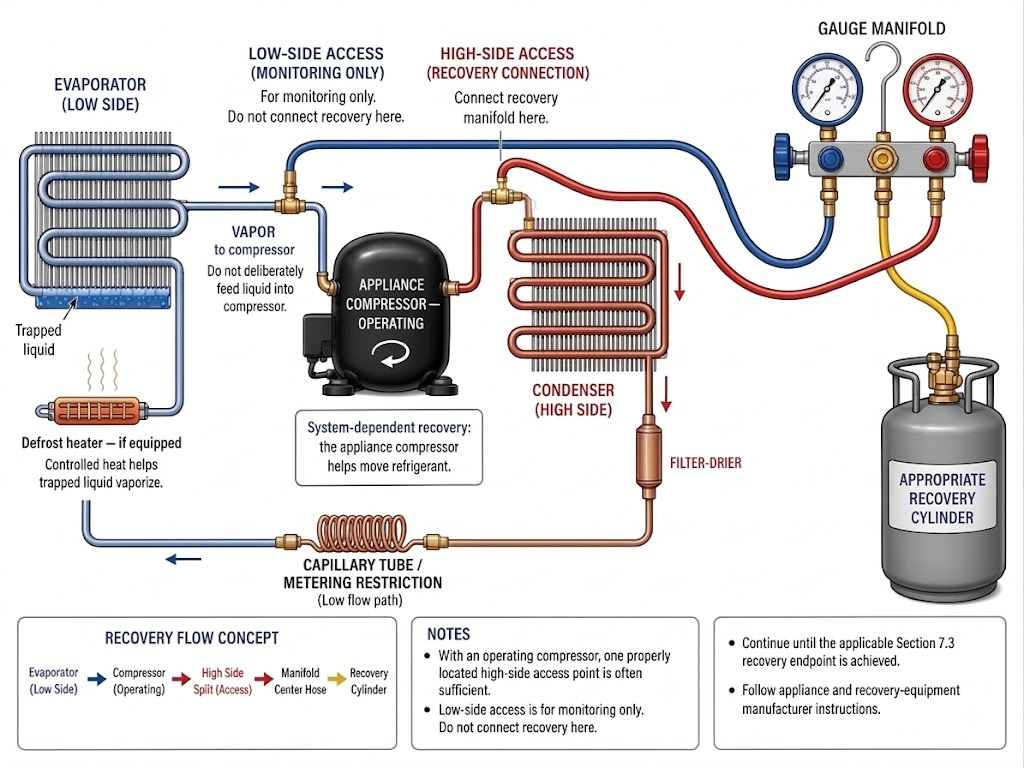
Figure 7.6.1 – Failed-compressor Type I recovery uses both high- and low-side access because the appliance compressor cannot move refrigerant through the system.
AI-generated instructional figure: It may contain visual inaccuracies. Use the accompanying lesson text and cited authoritative sources to verify technical and regulatory details.
EPA 608 Exam Focus
High-Priority Memory Rule
For a system-dependent recovery device:
COMPRESSOR OPERATIVE
→ operate it
COMPRESSOR INOPERATIVE
→ access BOTH high and low sides
This is one of the most important Type I recovery distinctions.
Failed-Compressor Technique Memory Aid
FAILED COMPRESSOR
→ BOTH-SIDE ACCESS
→ CONTROLLED HEAT
→ TAP / SHARPLY STRIKE COMPRESSOR
→ VAPORIZE TRAPPED REFRIGERANT
→ CONTINUE RECOVERY
The striking/tapping step is a recovery aid, not destructive work.
Defrost-Heater Memory Aid
cold evaporator
→ liquid refrigerant remains
→ approved defrost heat
→ refrigerant vaporizes
→ recovery improves
Remember the condition:
if equipped and permitted
Vacuum-Pump Type I Memory Aid
VACUUM PUMP
+
NONPRESSURIZED RECOVERY CONTAINER
→ special Type I system-dependent example
Do not confuse this with:
VACUUM PUMP
→ ordinary self-contained recovery machine
or:
VACUUM PUMP
→ intentional refrigerant venting
Both are incorrect.
Recovery Endpoint Memory Aid
For recovery equipment manufactured on or after November 15, 1993:
compressor functioning
→ 90%
compressor NOT functioning
→ 80%
Alternative:
4 in. Hg vacuum
Do not attach the November 15, 1993 date to the appliance itself.
Common Exam Wording
Watch for phrases such as:
inoperative compressorsystem-dependent recoverypassive recoveryboth high and low side accessheat and sharply strike compressornonpressurized recovery containervacuum pumpdefrost heater80 percent4 inches of mercury vacuum
The exact wording often signals which Type I recovery concept is being tested.
Exam-Clue Table
| Exam clue | Best concept |
|---|---|
| Compressor operates | Use it when performing system-dependent recovery |
| Compressor does not operate | Both high and low side access |
| Refrigerant trapped in compressor oil | Controlled heat / tapping can help release it |
| Refrigerant trapped in cold evaporator | Approved heat / defrost heater can help vaporize it |
| Vacuum pump + nonpressurized container | Special Type I system-dependent recovery example |
| Vacuum pump exhausts refrigerant | Incorrect — recovery must contain refrigerant |
| Post-1993 equipment + failed compressor | 80% recovery |
| Post-1993 equipment + functioning compressor | 90% recovery |
| Small-appliance alternative endpoint | 4 in. Hg vacuum |
| Recovery technique complete but endpoint not reached | Continue recovery |
| Failed compressor + one-side access only | Incomplete Type I failed-compressor concept |
Common Mistakes and Confusing Points
Mistake 1: Using Only the High Side Because Figure 7.5.1 Did
Section 7.5 covers an operating compressor.
Section 7.6 covers a failed compressor.
EPA’s Type I test topics specifically emphasize both high- and low-side access for the failed-compressor case.
Mistake 2: Using Only the Low Side
A low-side-only connection can leave high-side refrigerant dependent on migration through the capillary tube or other restrictions.
Both sides should be connected for the failed-compressor system-dependent recovery concept.
Mistake 3: Connecting the Blue Hose to a High-Side Process Stub
Hose color does not change the physical system.
Trace the refrigeration circuit first.
Then connect the blue hose to the low-side access.
Mistake 4: Connecting the Red Hose to the Suction Line
The red/high manifold connection belongs to the high-side access.
The suction line is low side.
Mistake 5: Drawing the Refrigeration Components in the Wrong Order
The basic small-appliance cycle remains:
compressor
→ condenser
→ metering restriction
→ evaporator
→ compressor
A failed compressor changes recovery behavior, not the physical order of components.
Mistake 6: Showing the Failed Compressor Pumping Refrigerant
If the compressor is failed:
compressor pumping arrow
→ wrong
The recovery path should bypass dependence on compressor pumping.
Mistake 7: Assuming Pressure at One Side Represents the Entire Appliance
Restrictions can prevent rapid equalization.
A pressure reading at one access point may not reveal refrigerant trapped on the opposite side.
This is another reason both-side access matters.
Mistake 8: Treating a Capillary Tube as an Open Pipe
A capillary tube is intentionally restrictive.
It can make passive pressure equalization and refrigerant migration very slow.
Mistake 9: Assuming a Failed Compressor Contains No Refrigerant
Refrigerant can remain in the compressor shell and oil.
Controlled heat and tapping can help release it.
Mistake 10: Using an Open Flame to Heat the Compressor
Open flames create fire and decomposition hazards.
Use only an approved controlled heat method.
Mistake 11: Interpreting “Sharply Strike” as “Break the Compressor”
EPA’s phrase describes a recovery technique.
It does not authorize damage, puncturing, or refrigerant release.
Mistake 12: Assuming Every Appliance Has a Defrost Heater
Only use the defrost-heater concept:
if equipped
+
if permitted by procedure
Mistake 13: Treating a Vacuum Pump as a General Recovery Machine
A vacuum pump is normally an evacuation/dehydration tool.
The Type I failed-compressor material contains a narrow special example using a vacuum pump with a nonpressurized recovery container.
Keep the contexts separate.
Mistake 14: Connecting a Vacuum Pump and Intentionally Venting Refrigerant
That defeats the purpose of recovery.
The refrigerant must be captured in the approved recovery arrangement.
Mistake 15: Substituting a Pressurized Recovery Cylinder for the Nonpressurized-Container Exam Example
The EPA Type I example specifically identifies a nonpressurized recovery container.
A pressurized recovery-cylinder arrangement is a different recovery configuration and is developed in Section 7.7.
Mistake 16: Using an Improvised Nonpressurized Container
The phrase does not mean “any container.”
Use only the container and arrangement appropriate to the certified recovery device.
Mistake 17: Saying Every Failed-Compressor Recovery Must Use a Vacuum Pump
EPA lists the vacuum-pump/nonpressurized-container arrangement as an example of a system-dependent method.
It is not the only possible recovery method.
A self-contained recovery machine can recover refrigerant without relying on the appliance compressor and is covered in Section 7.7.
Mistake 18: Applying 90% to a Failed Compressor With Post-1993 Recovery Equipment
For equipment manufactured on or after November 15, 1993:
failed appliance compressor
→ 80%
not 90%.
Mistake 19: Thinking 80% Is the Only Possible Endpoint
The current rule also provides the 4 in. Hg vacuum alternative when using applicable certified equipment.
Mistake 20: Applying November 15, 1993 to the Appliance Manufacture Date
The date distinction applies to the recovery equipment.
Mistake 21: Assuming the 15-lb System-Dependent Limit Defines Type I
It does not.
Small appliance:
factory manufactured
+
factory charged
+
hermetically sealed
+
5 lb or less
The 15-lb value is a limitation on ordinary system-dependent recovery equipment use.
Mistake 22: Stopping as Soon as Pressure Falls Once
Trapped refrigerant may continue to boil out of oil or cold components.
Follow the certified recovery-device procedure and verify the required endpoint.
Mistake 23: Assuming Pressure Rebound Always Means an Air Leak
In recovery, pressure rebound can come from refrigerant vaporizing after the system warms.
Interpret the complete situation.
Mistake 24: Heating a Recovery Container to Speed the Process
This section’s heat discussion is primarily about helping refrigerant vaporize inside the appliance.
Do not create an unsafe recovery-container condition.
Mistake 25: Confusing Recovery With Deep Evacuation
Type I recovery removes and captures refrigerant.
Deep evacuation/dehydration removes air and moisture after refrigerant recovery and repair.
The special vacuum-pump Type I recovery example does not erase that distinction.
Concept-Check Questions
Question 1
Why is recovery generally more difficult when the compressor in a small appliance is inoperative?
A. The compressor can no longer provide pumping assistance to move refrigerant through the appliance.
B. The condenser automatically becomes part of the low side.
C. The refrigerant immediately becomes noncondensable.
D. The appliance is no longer covered by Type I.
Question 2
When using a system-dependent recovery method on a small appliance with an inoperative compressor, what access arrangement does EPA’s Type I test-topic framework emphasize?
A. High-side access only
B. Low-side access only
C. Both high-side and low-side access
D. No access fitting is needed
Question 3
Why is access to both sides useful when the compressor has failed?
A. It allows refrigerant to reach the recovery path without depending on movement through the failed compressor and restrictive metering device.
B. It changes the appliance into a Type II appliance.
C. It increases the refrigerant charge.
D. It allows refrigerant to be intentionally vented from one side.
Question 4
What is the purpose of controlled heat during failed-compressor recovery?
A. To permanently increase the appliance operating pressure
B. To help trapped liquid or dissolved refrigerant vaporize and move toward the recovery path
C. To melt the compressor shell
D. To replace the recovery device
Question 5
EPA Type I test topics mention heating and sharply striking the compressor. What is the intended concept?
A. Damage the compressor so refrigerant escapes faster.
B. Help release refrigerant trapped in the compressor shell and oil while keeping the refrigerant contained.
C. Break the compressor discharge tube.
D. Create sparks to warm the shell.
Question 6
When can a defrost heater be useful during failed-compressor recovery?
A. When it is equipped and safely permitted to warm the evaporator and help trapped refrigerant vaporize
B. Only after the system has been opened to atmosphere
C. Only when oxygen is added to the system
D. It must be used on every Type I appliance
Question 7
Which statement about a vacuum pump is most accurate for this section?
A. A vacuum pump is always a self-contained refrigerant recovery machine.
B. EPA Type I test topics include a special system-dependent arrangement using a vacuum pump with a nonpressurized recovery container.
C. A vacuum pump may intentionally exhaust refrigerant during normal recovery.
D. A vacuum pump eliminates the need for recovery equipment certification.
Question 8
In the special EPA Type I failed-compressor example, what type of recovery container is associated with vacuum-pump assistance?
A. An open bucket
B. A nonpressurized recovery container used as part of the appropriate recovery arrangement
C. An oxygen cylinder
D. Any sealed disposable cylinder
Question 9
Recovery equipment was manufactured in 2025 and is being used on a small appliance whose compressor is not functioning. Which percentage-recovery requirement applies under the current small-appliance percentage pathway?
A. 25%
B. 50%
C. 80%
D. 90%
Question 10
Which alternative current small-appliance recovery endpoint can be used when the applicable certified equipment and procedure allow it?
A. 0 psig only
B. 4 in. Hg vacuum
C. 15 in. Hg vacuum
D. 25 mm Hg absolute
Question 11
Which statement correctly describes the November 15, 1993 date in the Type I recovery rules?
A. It is the required manufacture date of the small appliance.
B. It distinguishes categories of recovery equipment based on when that equipment was manufactured or imported.
C. It is the date every small-appliance compressor became hermetic.
D. It determines whether a defrost heater may be used.
Question 12
A technician connects only to the low side of a small appliance with a failed compressor and a capillary tube. What is the main concern?
A. Refrigerant on the high side may migrate only slowly through internal restrictions and may remain difficult to recover.
B. The low side automatically becomes high pressure.
C. The capillary tube increases refrigerant charge during recovery.
D. The appliance becomes an MVAC-like appliance.
Answers and detailed explanations will be included in
7.12 - Answers and Explanations.md.
Section Summary
When the compressor in a Type I small appliance is inoperative, the appliance cannot use its compressor to help move refrigerant.
That changes the recovery strategy.
The essential failed-compressor relationship is:
COMPRESSOR FAILED
→ no compressor pumping assistance
→ connect BOTH high side and low side
Both-side access prevents the recovery process from depending on refrigerant migrating through the failed compressor or restrictive capillary tube.
Refrigerant may remain trapped:
- In compressor oil.
- In the compressor shell.
- In a cold evaporator.
- In the condenser.
- Behind restrictions.
- In tubing low points.
Appropriate controlled heat can help trapped refrigerant vaporize.
EPA’s Type I test-topic framework specifically identifies:
heat + sharply strike compressor
and:
vacuum pump + nonpressurized recovery container
as examples used in recovery from small appliances with inoperative compressors.
These are controlled recovery concepts.
They do not authorize:
- Damaging the compressor.
- Using open flame.
- Improvised recovery containers.
- Intentional refrigerant venting.
- Treating an ordinary vacuum pump as a general self-contained recovery machine.
If an appliance defrost heater is equipped and its use is permitted:
defrost heat
→ warms cold evaporator
→ promotes vaporization
→ assists recovery
The recovery endpoint remains the applicable Section 7.3 requirement.
For recovery equipment manufactured on or after November 15, 1993:
compressor not functioning
→ 80% recovery
or the applicable certified alternative:
4 in. Hg vacuum
The most important exam distinction is:
OPERATING compressor
→ operate compressor during system-dependent recovery
versus:
FAILED compressor
→ access BOTH high and low sides
→ use approved techniques to free trapped refrigerant
The next section changes recovery equipment rather than appliance condition.
See Section 7.7 - Self-Contained Recovery.
References
Current EPA and Regulatory Sources
-
U.S. Environmental Protection Agency, Section 608 Test Topics, Type I Recovery Requirements and Recovery Techniques, current page verified August 11, 2026.
https://www.epa.gov/section608/test-topics -
Electronic Code of Federal Regulations, 40 CFR § 82.152 - Definitions, including
small appliance,self-contained recovery equipment, andsystem-dependent recovery equipment, verified August 11, 2026.
https://www.ecfr.gov/current/title-40/chapter-I/subchapter-C/part-82/subpart-F/section-82.152 -
Electronic Code of Federal Regulations, 40 CFR § 82.156 - Proper evacuation of refrigerant from appliances, especially paragraphs (b), (e), and (g), verified August 11, 2026.
https://www.ecfr.gov/current/title-40/chapter-I/subchapter-C/part-82/subpart-F/section-82.156 -
Electronic Code of Federal Regulations, 40 CFR § 82.158 - Standards for recovery and/or recycling equipment, especially small-appliance equipment requirements, verified August 11, 2026.
https://www.ecfr.gov/current/title-40/chapter-I/subchapter-C/part-82/subpart-F/section-82.158 -
U.S. Environmental Protection Agency, Refrigerant Recovery and Recycling Equipment Certification, current page verified August 11, 2026.
https://www.epa.gov/section608/refrigerant-recovery-and-recycling-equipment-certification
EPA 608 Teaching Reference
- International Training Institute for the Sheet Metal and Air Conditioning Industry, EPA Section 608 Study Guide, Type I recovery material. Used as a supplemental teaching reference; current EPA and eCFR requirements control where the older study material differs from current requirements.
HVAC Technical Background
- Rex Miller and Mark R. Miller, HVAC Licensing Study Guide, 3rd ed., supplemental refrigeration-cycle, compressor, capillary-tube, electrical-safety, and refrigerant-handling background.