9.2 - Low-Pressure Chiller Components
Module: Type III Low-Pressure Appliances
Technical and examination-topic verification date: August 13, 2026
Primary current authority: Current Section 608 Type III test-topic framework and current Section 608 technician-certification requirements
Course role: Identifies the major refrigerant-side, water-side, service, protection, lubrication, purge, and machinery-room monitoring components that students must recognize before studying Type III purge operation, leak testing, recovery, charging, evacuation, and safety
Learning Objectives
After completing this section, a student should be able to:
- Identify the evaporator, condenser, and centrifugal compressor on a typical low-pressure centrifugal chiller.
- Explain the basic refrigerant state and heat-transfer function associated with the evaporator and condenser.
- Explain the function of the water boxes and distinguish the chilled-water circuit from the condenser-water circuit.
- Explain the basic purpose of the purge unit and why it is associated with low-pressure chillers that can admit air.
- Explain the safety role of a rupture disc or other approved pressure-relief protection without treating it as a normal pressure-control device.
- Identify the evaporator charging valve/service connection and explain why it is important in later Type III charging procedures.
- Describe the basic functions of a conventional centrifugal-chiller oil system and recognize that some modern centrifugal chillers use oil-free bearing designs.
- Explain the role of a machinery-room refrigerant monitor and distinguish it from a pressure sensor inside the refrigerant circuit.
- Trace the simplified relationship among the major chiller components without confusing refrigerant flow with chilled-water or condenser-water flow.
- Recognize which component details are manufacturer-specific and must not be replaced by one universal service arrangement.
Introduction
Section 9.1 introduced the low-pressure centrifugal chiller as the principal equipment model for Type III examination preparation.
A technician now needs to move from the general refrigeration-cycle picture to the physical parts of the machine.
A typical water-cooled centrifugal chiller contains three major refrigeration components:
EVAPORATOR
→ CENTRIFUGAL COMPRESSOR
→ CONDENSER
plus several components that make low-pressure operation practical and safe:
- Purge unit.
- Pressure-relief or rupture-disc protection.
- Water boxes.
- Charging/service connection.
- Oil-lubrication system on applicable compressor designs.
- Refrigerant-monitoring equipment in the machinery-room environment.
These components do not all perform the same kind of job.
Some transfer heat.
Some move refrigerant.
Some manage water.
Some remove noncondensables.
Some protect the equipment against abnormal pressure.
Some support compressor lubrication.
Some protect people in the machinery room.
A useful first classification is:
| Component Group | Main Examples | Primary Purpose |
|---|---|---|
| Refrigeration-cycle components | Evaporator, compressor, condenser | Move heat and refrigerant through the cycle |
| Water-side components | Water boxes, tubes | Carry chilled water or condenser water through heat exchangers |
| Low-pressure support components | Purge unit | Remove accumulated noncondensables while minimizing refrigerant loss |
| Service components | Charging valve / service connection | Controlled refrigerant access for approved service procedures |
| Protection components | Rupture disc / relief device | Protect refrigerant-containing equipment from dangerous overpressure |
| Compressor-support components | Oil reservoir, pump, heater/cooler, filters, bearings | Lubricate and protect applicable compressor designs |
| Machinery-room safety components | Refrigerant monitor | Detect abnormal refrigerant concentration in room air and support alarm/ventilation response |
Understanding what each component does is more useful than memorizing one manufacturer’s exact physical arrangement.
Key Concepts
1. Evaporator
The evaporator is the chiller heat exchanger in which refrigerant absorbs heat from the chilled-water circuit.
In a typical low-pressure centrifugal chiller:
warmer chilled water enters evaporator water side
→ heat passes through tube walls
→ low-pressure refrigerant absorbs heat
→ refrigerant boils
→ cooler chilled water leaves
The refrigerant and water do not normally mix.
They are separated by the heat-exchanger tube walls.
Refrigerant Condition
The evaporator contains low-pressure refrigerant at conditions that allow boiling at the required chilled-water temperature.
Depending on chiller design, the evaporator can be a flooded shell-and-tube heat exchanger, with refrigerant surrounding the tubes while chilled water flows inside the tubes.
For exam preparation, remember:
EVAPORATOR
→ absorbs heat
→ refrigerant boils
→ chilled water is cooled
Why the Evaporator Matters in Type III Service
The evaporator is central to several later Type III procedures because it is associated with:
- Subatmospheric refrigerant pressure during normal operation.
- Chilled-water tubes that must be protected from freezing during deep refrigerant recovery.
- The evaporator charging connection used in later charging procedures.
- Possible water-side tube leakage into the refrigerant circuit.
Detailed freeze prevention is reserved for Section 9.6.
Detailed recharging is reserved for Section 9.8.
2. Condenser
The condenser is the chiller heat exchanger in which refrigerant rejects heat to condenser water.
The simplified sequence is:
higher-pressure refrigerant vapor enters condenser
→ heat passes through tube walls
→ condenser water absorbs heat
→ refrigerant condenses to liquid
The condenser-water circuit then carries the rejected heat toward a cooling tower or other heat-rejection device.
For exam preparation:
CONDENSER
→ rejects heat
→ refrigerant condenses
→ condenser water becomes warmer
Condenser and Noncondensables
Air that enters a low-pressure chiller can migrate to regions where it does not condense with the refrigerant.
Noncondensables commonly accumulate in the condenser/high-side region and can interfere with heat rejection.
This is why the purge system is typically connected to a location selected to remove noncondensables from the condenser region.
The exact purge connection and internal arrangement are manufacturer-specific.
Detailed purge operation is reserved for Section 9.3.
3. Centrifugal Compressor
The centrifugal compressor raises refrigerant-vapor pressure so the refrigerant can reject heat in the condenser.
A centrifugal compressor is a dynamic compressor.
A high-speed impeller adds velocity and energy to the refrigerant vapor. The diffuser or associated flow path converts part of that velocity into increased static pressure.
The simplified sequence is:
low-pressure vapor from evaporator
→ compressor inlet
→ impeller adds energy
→ pressure rises
→ higher-pressure vapor goes to condenser
Important State Rule
The compressor is intended to receive refrigerant primarily as:
VAPOR
not bulk liquid.
For a basic Type III component question:
EVAPORATOR
→ vapor to compressor
COMPRESSOR
→ higher-pressure vapor to condenser
Compressor Construction Varies
Centrifugal chillers can use different arrangements, including:
- Hermetic motor-compressor designs.
- Semi-hermetic arrangements.
- Open-drive designs.
- Gear-driven or direct-drive designs.
- Conventional oil-lubricated bearings.
- Modern oil-free magnetic-bearing or other oil-free designs.
Do not assume every centrifugal chiller has the same shaft seal, gearbox, oil pump, or motor arrangement.
The Type III examination emphasis is the function of the compressor and the associated service/safety concepts, not one brand’s construction.
4. Water Boxes
A water box is a chamber attached to the end of a shell-and-tube heat exchanger that directs water into or out of the heat-exchanger tubes.
A typical water-cooled centrifugal chiller has water boxes associated with both:
- The evaporator.
- The condenser.
Evaporator Water Boxes
Evaporator water boxes route:
CHILLED WATER
through the evaporator tubes.
The chilled-water circuit carries heat from the building or process to the chiller.
Condenser Water Boxes
Condenser water boxes route:
CONDENSER WATER
through the condenser tubes.
The condenser-water circuit carries heat away from the chiller toward the cooling tower or other heat-rejection equipment.
Water Box Versus Refrigerant Shell
This distinction is critical:
Water boxes + tube interiors
→ WATER SIDE
Space around tubes inside refrigerant shell
→ REFRIGERANT SIDE
Under normal operation, water and refrigerant are separated by the tube walls.
A tube failure can create communication between the two sides, which is why water-side isolation and tube-leak diagnosis matter in later Type III work.
Exam Trap
Do not assume that opening a water box automatically opens the refrigerant circuit.
The water box is normally on the water side.
However, a damaged tube or other internal failure can allow water and refrigerant spaces to communicate.
5. Purge Unit
A purge unit is used on applicable low-pressure chillers to remove accumulated noncondensable gases from the refrigerant system while minimizing refrigerant loss.
Section 9.1 established the reason it is needed:
subatmospheric refrigerant pressure
→ air can leak IN
→ noncondensables accumulate
The purge unit provides a controlled way to separate and remove those noncondensables.
Basic Purge Concept
Conceptually:
refrigerant vapor + noncondensables
→ purge unit
→ refrigerant is retained/recovered as much as practical
→ noncondensables are removed
The purge unit is not the component that creates the refrigeration effect.
It is also not a substitute for leak repair.
Purge Location
Because noncondensables tend to collect in the condenser/high-side region of a low-pressure chiller, the purge connection is commonly associated with that region.
Exact piping, purge reservoir design, control logic, and discharge management depend on the chiller manufacturer.
High-Priority Type III Relationship
Excessive purge operation
→ possible air infiltration
→ inspect for leaks
Detailed purge-unit thermodynamics, refrigerant recovery from purge discharge, and excessive-purge diagnostics are reserved for Section 9.3.
6. Rupture Disc and Pressure-Relief Protection
A low-pressure chiller is designed for relatively low refrigerant-side pressures compared with many Type II systems.
It therefore requires appropriate protection against abnormal overpressure.
One traditional protective device is a rupture disc, historically also called a frangible disc.
Basic Function
A rupture disc is designed to open when pressure reaches its rated condition.
Conceptually:
abnormal pressure rises
→ rupture disc reaches rated condition
→ disc opens
→ pressure is relieved through the designed relief path
The device protects the refrigerant-containing vessel from dangerous pressure buildup.
Important Safety Rule
A rupture disc is:
EMERGENCY OVERPRESSURE PROTECTION
It is not:
NORMAL PRESSURE CONTROL
A technician must not:
- Plug the relief opening.
- Cap the discharge in a way that defeats relief.
- Isolate required relief protection.
- Intentionally use the rupture disc as a routine pressure-control method.
- Raise test pressure merely to see whether the disc opens.
Do Not Memorize a Pressure Value Here
Specific rupture-disc and leak-test pressure values are important for Type III exam preparation.
Those values are covered in Section 9.4, together with the limits and conditions needed to interpret them correctly.
This section focuses only on the component’s function and identification.
Manufacturer Variation
Modern chillers can use different approved pressure-relief arrangements.
The exact:
- Device type.
- Location.
- Set/rated pressure.
- Discharge piping.
- Replacement procedure.
must follow the current equipment design, listing, manufacturer instructions, and applicable code.
7. Charging Valve / Service Connection
Low-pressure centrifugal chillers use designated refrigerant service connections for charging and recovery.
For Type III examination preparation, one especially important connection is the:
EVAPORATOR CHARGING VALVE
The current Type III test-topic framework specifically expects students to know that centrifugal chillers are charged through the evaporator charging valve.
Why the Evaporator Connection Matters
The evaporator charging connection provides controlled access to the low-pressure refrigerant side of the machine.
Later Type III charging procedure requires careful control of refrigerant phase because adding liquid refrigerant to a deeply evacuated low-pressure chiller can create a severe freezing hazard in water tubes.
Therefore, in this section remember only:
Type III centrifugal chiller
→ identify evaporator charging valve / service connection
The detailed sequence:
vapor first
→ raise pressure / saturation temperature safely
→ transition to liquid only when permitted
is reserved for Section 9.8.
Location Is Manufacturer-Specific
Many training diagrams show the charging connection at a low point on or near the evaporator.
Do not assume every manufacturer uses the identical physical orientation.
Identify the approved connection from:
- Chiller service manual.
- Permanent labels.
- Piping/service diagram.
- Manufacturer instructions.
8. Oil System
Many conventional centrifugal compressors use an oil system to lubricate bearings and, depending on design, gears and other moving surfaces.
A traditional oil system can include:
- Oil reservoir or sump.
- Oil pump.
- Oil filter.
- Oil heater.
- Oil cooler.
- Oil-pressure controls.
- Oil-temperature controls.
- Supply and return passages.
- Bearing lubrication points.
Basic Purpose
The oil system provides:
lubrication
+
cooling
+
clean oil supply
+
proper bearing protection
Refrigerant Can Dissolve in Oil
Low-pressure refrigerant can dissolve in compressor oil.
This matters during later recovery because refrigerant may remain in the oil after bulk liquid and vapor have been removed from other parts of the chiller.
Section 9.7 develops:
- Refrigerant dissolved in oil.
- Oil heating.
- Oil removal.
- Recovery completion.
Oil Heater Versus Crankcase Heater
Do not automatically apply the Type II reciprocating-compressor crankcase heater concept to every centrifugal chiller oil system.
The component arrangement and purpose can differ.
A centrifugal chiller oil heater may be used to maintain oil temperature and help manage refrigerant dissolved in the oil, but the exact control strategy is manufacturer-specific.
Modern Oil-Free Designs
Some modern centrifugal chillers use oil-free bearing technology.
Therefore:
Centrifugal chiller
≠
always has conventional oil pump and oil reservoir
For EPA 608 study purposes, the traditional oil-system concepts remain important because they are directly connected to refrigerant recovery from oil.
9. Refrigerant Monitor
A refrigerant monitor is a machinery-room safety device that detects refrigerant in the surrounding room air.
It is not normally part of the sealed refrigerant flow path.
This distinction is important:
REFRIGERANT PRESSURE SENSOR
→ measures pressure in refrigerant system
ROOM REFRIGERANT MONITOR
→ samples/detects refrigerant in machinery-room air
Why It Is Needed
A refrigerant release into a machinery room can create hazards such as:
- Oxygen displacement.
- Exposure to refrigerant vapor.
- Other refrigerant-specific hazards.
A monitoring system can be integrated with:
- Alarm functions.
- Mechanical ventilation.
- Building/facility safety response.
The exact current machinery-room requirements, detector arrangement, alarm response, and applicable safety-standard/code provisions are reserved for Section 9.10.
Exam-Relevant Recognition
For Type III preparation, recognize the relationship:
low-pressure chiller machinery room
→ refrigerant monitoring / alarm / ventilation safety concept
Do not memorize one universal detector height, concentration setpoint, or alarm sequence from this section.
Component Relationships
1. Refrigerant-Side Relationship
A simplified refrigerant path is:
EVAPORATOR
→ low-pressure refrigerant vapor
→ CENTRIFUGAL COMPRESSOR
→ higher-pressure refrigerant vapor
→ CONDENSER
→ liquid refrigerant
→ refrigerant flow-control / pressure-reducing path
→ EVAPORATOR
The purge system connects to the refrigerant system for the separate purpose of removing noncondensables.
The rupture-disc/relief device connects to the refrigerant-containing equipment for abnormal-pressure protection.
The charging valve provides controlled service access.
2. Water-Side Relationship
The chiller normally has two separate water circuits.
Chilled-Water Circuit
building / process
→ warmer chilled water
→ EVAPORATOR WATER BOX
→ evaporator tubes
→ cooler chilled water
→ building / process
Condenser-Water Circuit
cooling tower / heat rejection
→ cooler condenser water
→ CONDENSER WATER BOX
→ condenser tubes
→ warmer condenser water
→ cooling tower / heat rejection
Do not connect the chilled-water circuit directly to the condenser in a normal water-cooled chiller schematic.
Do not connect the condenser-water circuit directly to the evaporator.
3. Chiller Component Functional Map
| Component | Refrigerant Side, Water Side, or Room? | Main Function | High-Priority Exam Association |
|---|---|---|---|
| Evaporator | Refrigerant + chilled-water heat exchanger | Refrigerant absorbs heat and boils | Chilled-water cooling; charging connection; freeze concern |
| Condenser | Refrigerant + condenser-water heat exchanger | Refrigerant rejects heat and condenses | Heat rejection; noncondensables/purge region |
| Centrifugal compressor | Refrigerant side | Raises vapor energy and pressure | Vapor compression |
| Purge unit | Connected to refrigerant system | Removes noncondensables while minimizing refrigerant loss | Excessive purging can indicate leakage |
| Rupture disc / relief device | Refrigerant-side protection | Emergency overpressure relief | Do not defeat relief protection |
| Water boxes | Water side | Direct water through heat-exchanger tubes | Chilled-water vs condenser-water distinction |
| Evaporator charging valve | Refrigerant service connection | Controlled refrigerant access | Charge centrifugals through evaporator charging valve |
| Oil system | Compressor support | Lubrication/cooling on applicable designs | Refrigerant can remain dissolved in oil |
| Refrigerant monitor | Machinery-room air | Detects abnormal refrigerant concentration | Alarm/ventilation safety concept |
Technical and Service Details
1. Shell-and-Tube Heat Exchangers
Many traditional water-cooled centrifugal chillers use shell-and-tube evaporators and condensers.
The general arrangement is:
Water
→ inside tubes
and:
Refrigerant
→ shell side around tubes
This arrangement allows heat transfer without intentional mixing.
Evaporator
In a flooded evaporator, liquid refrigerant surrounds a large portion of the tube bundle and boils as it absorbs heat from chilled water.
Condenser
In the condenser, refrigerant vapor rejects heat to the condenser-water tubes and condenses.
Exact tube-pass arrangements, shell configurations, refrigerant levels, and flow-control systems vary by manufacturer.
2. Why Water Boxes Are Service-Relevant
Water boxes provide access to the water side for tasks such as:
- Tube inspection.
- Tube cleaning.
- Tube testing.
- Water-side maintenance.
Before opening a water box, technicians must follow the appropriate water-system isolation and safety procedure.
The fact that a water box is on the water side does not eliminate hazards from:
- Pressurized water.
- Hot or cold water.
- Chemical water treatment.
- Unexpected water flow.
- Possible refrigerant communication through a failed tube.
Detailed water-side and machinery-room safety is developed later.
3. Purge Unit Is a Symptom-Management Device, Not the Root-Cause Repair
A useful troubleshooting distinction is:
PURGE UNIT
→ removes accumulated noncondensables
while:
LEAK REPAIR
→ stops the path allowing air/moisture into the chiller
Therefore:
Frequent purge cycles
→ investigate leakage
not merely:
Frequent purge cycles
→ purge is doing its job, ignore the condition
The detailed leak relationship is developed in Section 9.3.
4. Rupture Disc Is Not a Service Port
A rupture-disc assembly must not be confused with:
- Charging connection.
- Recovery port.
- Purge discharge.
- Drain valve.
- Normal pressure-control valve.
It is a dedicated safety device.
If a rupture disc has opened, the technician must treat the event as an abnormal-pressure/safety condition and follow the equipment manufacturer’s inspection and replacement procedure.
Do not simply reseal the opening with an ordinary cap or valve.
5. Service Connections Must Be Positively Identified
Large chillers can have multiple connections for:
- Refrigerant charging.
- Refrigerant recovery.
- Oil service.
- Purge service.
- Pressure measurement.
- Water drain/vent.
A technician should not identify a connection solely by its apparent size or location.
Use:
- Permanent labels.
- Manufacturer service diagram.
- Current service manual.
- Valve identification.
Connecting recovery or charging equipment to the wrong port can create:
- Incorrect refrigerant phase flow.
- Oil removal.
- Water contamination.
- Equipment damage.
- Unsafe pressure conditions.
6. Keep Refrigerant, Oil, and Water Systems Conceptually Separate
A centrifugal chiller can contain several fluid systems at once:
REFRIGERANT
CHILLED WATER
CONDENSER WATER
OIL (on applicable compressor designs)
These fluids normally occupy different circuits.
A strong Type III technician should be able to identify which fluid belongs to which component before opening any connection.
Important Terms
Centrifugal Compressor
A centrifugal compressor is a dynamic compressor that uses one or more rotating impellers to add energy to refrigerant vapor and raise its pressure through the compressor/diffuser flow path.
Charging Valve
A charging valve is a designated refrigerant service connection used to introduce refrigerant according to the equipment manufacturer’s charging procedure. Type III exam preparation emphasizes the evaporator charging valve on centrifugal chillers.
Condenser
The condenser is the refrigerant heat exchanger where higher-pressure refrigerant rejects heat and condenses while condenser water carries the rejected heat away.
Condenser Water Box
A condenser water box directs condenser water into or out of the condenser tube bundle.
Evaporator
The evaporator is the refrigerant heat exchanger where low-pressure refrigerant absorbs heat and boils while chilled water is cooled.
Evaporator Water Box
An evaporator water box directs chilled water into or out of the evaporator tube bundle.
Oil System
An oil system supplies, conditions, filters, heats/cools, and returns lubricating oil for applicable centrifugal-compressor bearing and drive components. Exact components vary by design.
Purge Unit
A purge unit removes accumulated noncondensable gases from an applicable low-pressure refrigerant system while minimizing refrigerant loss.
Refrigerant Monitor
A refrigerant monitor is machinery-room detection equipment used to detect abnormal refrigerant concentration in ambient room air and support the required safety response.
Rupture Disc
A rupture disc is a non-reclosing pressure-relief device designed to open at its rated condition to protect refrigerant-containing equipment from dangerous overpressure.
Water Box
A water box is a chamber at the end of a shell-and-tube heat exchanger that distributes water into or collects water from the heat-exchanger tubes.
Figures and Diagrams
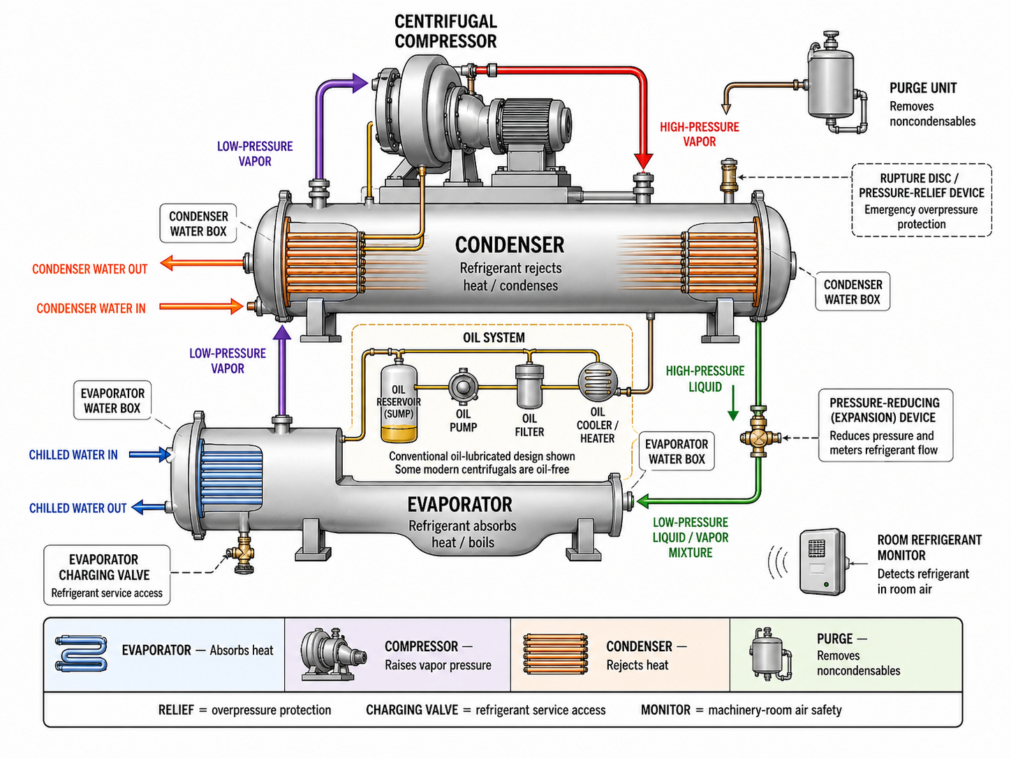
Figure 9.2.1 - Major refrigeration, water-side, service, protection, lubrication, purge, and monitoring components associated with a low-pressure centrifugal chiller.
AI-generated instructional figure: It may contain visual inaccuracies. Use the accompanying lesson text and cited authoritative sources to verify technical and regulatory details.
EPA 608 Exam Focus
What Students Must Remember
- The evaporator absorbs heat from chilled water and boils refrigerant.
- The condenser rejects heat to condenser water and condenses refrigerant.
- The centrifugal compressor raises refrigerant-vapor pressure.
- The compressor receives vapor, not bulk liquid.
- Water boxes are part of the water side of shell-and-tube heat exchangers.
- Evaporator water boxes carry chilled water.
- Condenser water boxes carry condenser water.
- Water and refrigerant are normally separated by tube walls.
- A purge unit removes noncondensables from an applicable low-pressure chiller while minimizing refrigerant loss.
- Excessive purging can be a sign of air leakage into the chiller.
- A rupture disc / relief device protects against abnormal overpressure.
- A rupture disc is not a normal pressure-control or service valve.
- Type III test preparation emphasizes the evaporator charging valve on centrifugal chillers.
- Many traditional centrifugal chillers use an oil system for compressor bearings and related components.
- Refrigerant can remain dissolved in oil; detailed recovery from oil is covered later.
- Some modern centrifugal chillers are oil-free, so do not assume every centrifugal machine has the same oil circuit.
- A refrigerant monitor detects refrigerant in machinery-room air; it is not a refrigerant pressure sensor inside the chiller.
High-Priority Component Relationships
EVAPORATOR
→ absorbs heat
→ refrigerant boils
CENTRIFUGAL COMPRESSOR
→ receives vapor
→ raises vapor pressure
CONDENSER
→ rejects heat
→ refrigerant condenses
PURGE UNIT
→ removes noncondensables
RUPTURE DISC / RELIEF
→ emergency overpressure protection
EVAPORATOR CHARGING VALVE
→ Type III refrigerant service access
ROOM REFRIGERANT MONITOR
→ detects refrigerant in machinery-room air
Typical Exam Question Patterns
Students may be asked to:
- Identify which component cools chilled water.
- Identify which component rejects heat to condenser water.
- Identify the function of the centrifugal compressor.
- Distinguish chilled-water and condenser-water circuits.
- Identify the purpose of the purge unit.
- Recognize excessive purge operation as a possible leak indication.
- Identify a rupture disc as pressure-relief protection.
- Identify the evaporator charging valve as the Type III centrifugal charging connection.
- Recognize refrigerant dissolved in oil as a later recovery concern.
- Distinguish a room refrigerant monitor from a refrigerant pressure sensor.
High-Risk Words
Pay particular attention to:
- Evaporator
- Condenser
- Water box
- Purge
- Noncondensable
- Rupture disc
- Relief
- Charging valve
- Oil
- Monitor
- Room air
- Vapor
- Liquid
Common Mistakes and Confusing Points
Mistake 1: Reversing the Evaporator and Condenser Water Circuits
The evaporator cools chilled water.
The condenser heats condenser water as refrigerant rejects heat.
Mistake 2: Thinking Water Boxes Contain Refrigerant During Normal Operation
Water boxes distribute water to the heat-exchanger tubes.
Refrigerant occupies the refrigerant side of the heat exchanger.
Mistake 3: Assuming the Compressor Receives Liquid Refrigerant
A centrifugal compressor is designed to compress vapor.
Bulk liquid entry is not the normal refrigerant state at the compressor inlet.
Mistake 4: Treating the Purge Unit as a Leak Repair
The purge unit removes noncondensables.
It does not repair the leak that allowed air to enter.
Mistake 5: Assuming Frequent Purging Is Normal and Needs No Investigation
A significant increase in purge activity can indicate increased air infiltration.
Mistake 6: Treating the Rupture Disc as a Normal Pressure-Control Valve
A rupture disc is emergency overpressure protection.
It is not intended for normal system regulation.
Mistake 7: Confusing the Rupture Disc With the Charging Valve
The relief device protects against abnormal pressure.
The charging valve is a controlled refrigerant service connection.
Mistake 8: Memorizing One Exact Charging-Valve Location for Every Chiller
Type III preparation emphasizes charging through the evaporator charging valve, but exact physical location and valve arrangement are manufacturer-specific.
Mistake 9: Assuming Every Centrifugal Chiller Has a Conventional Oil System
Many traditional machines do.
Some modern centrifugal chillers use oil-free bearing technology.
Mistake 10: Confusing an Oil Heater With a Type II Crankcase Heater
The systems can serve related refrigerant-management purposes but are not automatically identical in construction or control strategy.
Mistake 11: Thinking a Refrigerant Monitor Measures Chiller Pressure
A machinery-room refrigerant monitor detects refrigerant in room air.
It is not the chiller’s pressure gauge or transducer.
Mistake 12: Adding Detailed Purge, Charging, or Relief Numbers Too Early
Those numerical requirements and procedures belong in the later Type III sections where they can be verified and taught with their controlling conditions.
Concept-Check Questions
Question 9.2-1
Which component of a typical low-pressure centrifugal chiller absorbs heat from the chilled-water circuit?
A. Condenser
B. Evaporator
C. Purge unit
D. Rupture disc
Question 9.2-2
What is the principal function of the centrifugal compressor in the refrigerant cycle?
A. Raise the pressure and energy of refrigerant vapor
B. Store condenser water
C. Remove moisture from chilled water
D. Act as the machinery-room refrigerant detector
Question 9.2-3
Which statement correctly distinguishes the two main chiller water circuits?
A. Chilled water flows through the condenser, and condenser water flows through the evaporator.
B. Both water circuits normally mix inside the evaporator shell.
C. Chilled water passes through the evaporator, while condenser water passes through the condenser.
D. Condenser water is the refrigerant used by the compressor.
Question 9.2-4
What is the principal purpose of a purge unit on an applicable low-pressure chiller?
A. Increase compressor motor speed
B. Remove accumulated noncondensable gases while minimizing refrigerant loss
C. Replace the condenser-water pump
D. Control normal refrigerant pressure by opening to the atmosphere
Question 9.2-5
Which statement best describes a rupture disc on a low-pressure chiller?
A. It is a normal refrigerant charging valve.
B. It is a water-box drain valve.
C. It provides emergency overpressure protection.
D. It is the normal device used to regulate evaporator pressure.
Question 9.2-6
For Type III examination preparation, which service connection should be associated with charging a centrifugal chiller?
A. Evaporator charging valve
B. Rupture-disc outlet
C. Condenser-water drain
D. Refrigerant-monitor sampling point
Question 9.2-7
Which statement about a centrifugal-chiller oil system is most accurate?
A. Every centrifugal chiller must use an identical external oil pump.
B. Conventional oil-lubricated chillers use oil to protect bearings and related components, but some modern centrifugal chillers are oil-free.
C. Oil normally flows through the chilled-water tubes.
D. The oil system serves as the purge unit.
Question 9.2-8
What does a machinery-room refrigerant monitor primarily detect?
A. Refrigerant concentration in room air
B. Chilled-water flow through the evaporator
C. Oil level inside every centrifugal compressor
D. Condenser refrigerant saturation pressure
Answers and detailed explanations will be provided in
9.15 - Answers and Explanations.md.
Section Summary
A low-pressure centrifugal chiller combines refrigeration-cycle components with water-side, service, purge, lubrication, pressure-protection, and room-safety components.
The core refrigeration components are:
EVAPORATOR
→ absorbs heat and boils refrigerant
CENTRIFUGAL COMPRESSOR
→ raises refrigerant-vapor pressure
CONDENSER
→ rejects heat and condenses refrigerant
The water-side components include:
EVAPORATOR WATER BOXES
→ chilled water
and:
CONDENSER WATER BOXES
→ condenser water
Important Type III support and safety components include:
PURGE UNIT
→ removes noncondensables
RUPTURE DISC / RELIEF DEVICE
→ emergency overpressure protection
EVAPORATOR CHARGING VALVE
→ controlled refrigerant service access
OIL SYSTEM
→ lubricates applicable conventional compressor designs
ROOM REFRIGERANT MONITOR
→ detects refrigerant in machinery-room air
The next section develops one of the most distinctive Type III subsystems in detail:
Section 9.3 - Air Moisture and Purge Units.
References
Current EPA Sources
-
U.S. Environmental Protection Agency, Section 608 Test Topics, Type III low-pressure topics, verified August 13, 2026.
-
U.S. Environmental Protection Agency, Section 608 Technician Certification Requirements, Type III certification framework, verified August 13, 2026.
Project Technical References
-
International Training Institute for the Sheet Metal and Air Conditioning Industry, EPA Section 608 Study Guide, Type III low-pressure refrigeration notes and examination-preparation topics.
-
Edward G. Pita, Air Conditioning Principles and Systems: An Energy Approach, 4th ed., centrifugal compressor, water chiller, evaporator, condenser, and flooded-evaporator technical foundations.
-
Rex Miller and Mark R. Miller, HVAC Licensing Study Guide, 3rd ed., refrigeration components, pressure-relief principles, refrigerant-system service, and safety context.
-
Engineering Pro Guides, Mechanical PE HVAC and Refrigeration Textbook, current project copy, chilled-water, condenser-water, chiller, and shell-and-tube system context.