4.4 - Receivers Accumulators and Filter-Driers
Module: Refrigeration Cycle Components Gauges and Pressure-Temperature Relationships
Course role: Explains the location and function of receivers, suction accumulators, filter-driers, moisture indicators, and sight glasses in a vapor-compression refrigeration system
Learning Objectives
After completing this section, a student should be able to:
- Identify the normal location and primary function of a liquid receiver in a refrigeration system.
- Identify the normal location and primary function of a suction accumulator.
- Explain how an accumulator helps protect a compressor from uncontrolled liquid refrigerant return.
- Distinguish the receiver’s relationship to the metering device from the accumulator’s relationship to the compressor.
- Explain how a filter-drier removes moisture and solid contamination and why its capacity is limited.
- Interpret the purpose and limitations of sight glasses and moisture indicators without treating them as complete charging or contamination tests.
Introduction
The four-component vapor-compression cycle introduced in Sections 4.1–4.3 is the foundation of refrigeration:
Compressor
→ Condenser
→ Metering Device
→ Evaporator
→ Compressor
Real systems often include additional components that improve:
- Refrigerant storage.
- Liquid management.
- Compressor protection.
- Moisture control.
- Contaminant control.
- Serviceability.
- System monitoring.
Three especially important components are:
- Receiver — normally located on the high-pressure liquid side after the condenser.
- Accumulator — normally located on the low-pressure suction side after the evaporator and before the compressor.
- Filter-drier — commonly located in the liquid line to remove moisture and solid contamination.
A sight glass or moisture indicator may also be installed in the liquid line to help the technician observe refrigerant condition or moisture condition.
The most important comparison is:
Receiver
→ stores / manages HIGH-PRESSURE LIQUID
→ upstream of the metering device

Accumulator
→ separates / manages LOW-PRESSURE LIQUID AND VAPOR
→ upstream of the compressor
Both components can contain liquid refrigerant, but they serve very different purposes.
Key Concepts
1. Receiver and Accumulator Are Not Interchangeable
A receiver is associated with the high-side liquid circuit.
An accumulator is associated with the low-side suction circuit.
A useful comparison is:
| Component | Typical Location | Pressure Side | Primary Function |
|---|---|---|---|
| Receiver | After condenser, before metering device | High side | Stores and supplies liquid refrigerant |
| Accumulator | After evaporator, before compressor | Low side | Separates liquid from suction vapor and limits liquid return to compressor |
Therefore:
Receiver ≠ Accumulator
and:
Liquid storage on high side
≠
Liquid protection on suction side
2. Not Every System Uses Both Components
Some refrigeration systems use:
- A receiver but no accumulator.
- An accumulator but no receiver.
- Both.
- Neither as a separate external component.
The need depends on:
- System design.
- Refrigerant charge strategy.
- Metering device.
- Operating range.
- Heat-pump operation.
- Possibility of liquid return.
- Service and pump-down requirements.
Do not assume that every vapor-compression system must contain a receiver or accumulator.
The Liquid Receiver
1. Typical Location
A liquid receiver is normally installed on the high-pressure liquid side after the condenser.
A common arrangement is:
Compressor
→ Condenser
→ Receiver
→ Liquid line
→ Filter-drier / sight glass as applicable
→ Metering device
→ Evaporator
→ Compressor
The exact order of liquid-line accessories varies by system design.
For basic cycle reasoning:
Receiver location = after condenser and before metering device.
2. Primary Function
The receiver provides a place to collect and store liquid refrigerant.
It can:
- Hold variations in system refrigerant inventory.
- Supply liquid refrigerant to the liquid line and metering device.
- Provide storage capacity during certain operating or service conditions.
- Support pump-down arrangements when the system is specifically designed for pump-down.
The receiver is not the device that meters refrigerant into the evaporator.
The metering device still controls refrigerant flow into the evaporator.
3. Receiver Contains High-Pressure Refrigerant
Because the receiver is downstream of the condenser and upstream of the metering device, it is part of the high side.
The refrigerant in the receiver is predominantly liquid under normal operation.
Therefore:
Receiver
= High side
= Liquid storage
4. Receiver and the Metering Device
The receiver helps maintain a liquid supply to the liquid line and metering device.
A simplified path is:
Condenser
→ liquid refrigerant
→ Receiver
→ liquid line
→ Metering device
The metering device requires an appropriate inlet condition to control refrigerant flow properly.
A receiver does not create the pressure drop into the evaporator.
The metering device performs that function.
5. Receiver and Refrigerant Storage During Service
In systems designed for it, refrigerant may be moved into the receiver during a pump-down or certain service procedures.
This can allow selected downstream components to be isolated for service without transferring the entire charge to an external recovery cylinder.
However:
- Pump-down is not possible or appropriate on every system.
- The receiver must have adequate approved capacity.
- Service valves and controls must be arranged for the procedure.
- Refrigerant must not be trapped where thermal expansion can create unsafe pressure.
- The specific equipment service procedure controls.
A receiver should not be treated as an unlimited storage vessel.
6. Receiver Is Not Always Required
A receiver is common in many systems using expansion valves and systems that must accommodate refrigerant inventory changes.
Other designs may control charge without a separate receiver.
Examples can include some:
- Capillary-tube systems.
- Fixed-orifice systems.
- Factory-charged unitary equipment.
The absence of a receiver does not automatically indicate a system defect.
The Suction Accumulator
1. Typical Location
A suction accumulator is normally installed:
Evaporator outlet
→ Accumulator
→ Compressor inlet
Therefore, it is on the low-pressure side.
For basic reasoning:
Accumulator location = after evaporator and before compressor.
2. Primary Function
The accumulator protects the compressor by helping prevent uncontrolled liquid refrigerant from entering the compressor suction.
It receives refrigerant from the evaporator and separates:
- Vapor that can continue toward the compressor.
- Excess liquid that should not enter the compressor in a large uncontrolled quantity.
A simplified internal concept is:
Suction mixture enters accumulator
        ↓
Vapor separates from liquid
        ↓
Vapor leaves toward compressor
        ↓
Trapped liquid is returned gradually as the design permits
3. Why Liquid Protection Matters
A conventional compressor is designed primarily to compress vapor.
Large quantities of liquid refrigerant entering the compressor can cause:
- Liquid slugging.
- Valve damage.
- Mechanical stress.
- Bearing damage.
- Lubricant dilution.
- Loss of effective lubrication.
Therefore:
The accumulator is a compressor-protection device.
4. Accumulator Does Not Simply Store Liquid Forever
The accumulator is not intended to collect liquid indefinitely.
Its design normally allows controlled return of:
- Refrigerant.
- Lubricating oil.
back toward the compressor as operating conditions permit.
The exact internal design can include:
- Outlet tubes.
- Orifices.
- Oil-return holes.
- Screens.
- Internal baffles.
These details vary among manufacturers.
For exam preparation, focus on the main function:
Accumulator
→ separates excess suction liquid
→ protects compressor
5. Accumulator and the Evaporator
An accumulator is installed after the evaporator.
It does not meter the normal refrigerant flow entering the evaporator.
Correct sequence:
Metering device
→ Evaporator
→ Accumulator
→ Compressor
Therefore:
Metering device controls refrigerant entering evaporator
Accumulator manages refrigerant leaving evaporator before compressor
6. Accumulators in Heat Pumps and Variable Conditions
Suction accumulators are especially useful where operating conditions can increase the chance of liquid return.
Examples include some:
- Heat pumps.
- Systems with rapid load changes.
- Defrost transitions.
- Flooded or overfeed arrangements.
- Systems subject to refrigerant migration or floodback.
The presence and sizing of an accumulator are design decisions.
Do not add one based only on a general rule without engineering or manufacturer approval.
Receiver Versus Accumulator
High-Priority Comparison
| Feature | Receiver | Accumulator |
|---|---|---|
| Pressure region | High side | Low side |
| Typical location | After condenser | After evaporator |
| Relative position | Before metering device | Before compressor |
| Main refrigerant condition | High-pressure liquid | Low-pressure vapor with possible excess liquid |
| Main purpose | Store/manage liquid refrigerant | Protect compressor from liquid return |
| Direct compressor-liquid protection | No | Yes |
| Meters refrigerant into evaporator | No | No |
| May support refrigerant storage during service | Yes, if system is designed for it | Not its normal purpose |
Memory Aid
Receiver receives condenser LIQUID
Accumulator catches suction LIQUID before compressor
Another useful memory aid is:
R = Receiver = liquid Reserve
A = Accumulator = Ahead of compressor on suction side
The memory aid is only a study tool; the circuit location and function are the controlling concepts.
Liquid Refrigerant Protection of the Compressor
1. Normal Compressor Inlet Condition
The compressor should normally receive vapor.
From Section 4.2:
Evaporator outlet
→ low-pressure vapor
→ compressor inlet
In many systems, the vapor is somewhat superheated.
2. Liquid Floodback
Floodback refers to liquid refrigerant returning from the evaporator toward the compressor during operation.
Possible contributing conditions can include:
- Excess refrigerant feed.
- Low evaporator heat load.
- Metering-device malfunction or misadjustment.
- Airflow or water-flow problems at the evaporator.
- Rapid operating changes.
- Defrost or heat-pump transitions.
An accumulator can provide protection, but it does not correct the underlying cause of abnormal floodback.
3. Liquid Slugging
Liquid slugging occurs when a compressor attempts to handle a significant quantity of incompressible liquid.
The result can be severe mechanical damage.
Therefore:
Accumulator protection
≠
permission to ignore floodback
The cause of abnormal liquid return must still be diagnosed and corrected.
4. Superheat and Compressor Protection
Adequate vapor condition at the evaporator outlet is commonly evaluated using superheat where the system design and charging method call for it.
Superheat provides evidence that the refrigerant is vapor at the measurement point.
However:
- One universal superheat value does not apply to every system.
- Some system designs use different control strategies.
- An accumulator can be part of the protection strategy.
Detailed superheat measurement is covered in Section 4.8 - Superheat and Subcooling.
Filter-Driers
1. Purpose
A filter-drier performs two main contamination-control functions:
- Filtering solid particles.
- Drying the refrigerant circuit by removing moisture with desiccant.
Therefore:
Filter-drier
= Filter + Desiccant
2. Typical Liquid-Line Location
A liquid-line filter-drier is common in many refrigeration and air-conditioning systems.
A typical arrangement is:
Condenser / Receiver
→ Liquid line
→ Filter-drier
→ Sight glass as applicable
→ Metering device
The exact accessory order depends on system design.
The liquid-line filter-drier helps protect the metering device from:
- Dirt.
- Metal particles.
- Scale.
- Other solid contamination.
- Moisture that can freeze at a restriction.
3. Filter Function
Internal screens or filtering media capture solid contaminants before they reach sensitive components.
Particles can cause:
- Metering-device restriction.
- Valve damage.
- Wear.
- Poor refrigerant flow.
4. Drier Function
The desiccant removes moisture from refrigerant and oil circulating through the component.
Moisture control is important because water can contribute to:
- Ice formation at metering restrictions.
- Acid formation.
- Corrosion.
- Lubricant degradation.
- Copper plating.
- Compressor damage.
5. Moisture Capacity Is Limited
A filter-drier cannot absorb an unlimited amount of water.
As the desiccant approaches saturation:
- Drying effectiveness decreases.
- Moisture can remain in the system.
Therefore:
A filter-drier does not replace proper evacuation and dehydration.
Likewise:
Evacuation does not replace a required filter-drier.
The two processes are complementary.
6. A Filter-Drier Does Not Remove Air
A filter-drier removes:
- Moisture.
- Solid contaminants.
It does not remove:
- Air.
- Nitrogen.
- Other noncondensable gases.
Those gases are removed by proper evacuation after refrigerant recovery and system service.
7. Replacement Considerations
A filter-drier may need replacement when:
- The sealed system has been opened for major service.
- The drier has been exposed to atmosphere.
- Moisture contamination is suspected.
- The drier is restricted.
- A compressor has failed or burned out.
- A retrofit procedure requires replacement.
Follow the equipment, compressor, or filter-drier manufacturer’s service procedure.
Do not leave a replacement drier open to humid air longer than necessary before installation.
8. Suction-Line Filter-Driers
A filter-drier is not always a liquid-line component.
A suction-line filter-drier may be specified for:
- Compressor burnout cleanup.
- Acid removal.
- Severe contamination cleanup.
Because a suction-line filter-drier creates pressure drop, its use must follow the approved cleanup procedure.
It may require:
- Pressure-drop monitoring.
- Replacement after contamination is captured.
- Removal after cleanup.
Do not assume that a suction-line drier should be permanently added to every system.
Filter-Drier Restriction
1. Restriction Can Affect Refrigerant Flow
As contamination accumulates, a filter-drier can become restricted.
A restriction can produce:
- Excessive pressure drop.
- Reduced refrigerant flow.
- Flashing downstream of the restriction.
- Abnormal temperature change across the drier.
- Starved evaporator symptoms.
2. Temperature Difference Can Be a Clue
A significant temperature drop across a liquid-line filter-drier under steady refrigerant flow can be evidence of excessive pressure drop or restriction.
However:
Temperature difference alone does not prove the diagnosis.
The technician should evaluate:
- Pressure.
- Temperature.
- Refrigerant state.
- Load.
- Other possible restrictions.
3. Do Not Bypass a Required Filter-Drier
Removing a restricted drier and permanently connecting the line without the required replacement would remove contamination protection.
The correct service action is to:
- Correct the contamination problem.
- Install the proper replacement component.
- Evacuate as required.
- Verify operation.
Sight Glasses
1. Purpose
A sight glass provides a visual window into the refrigerant line.
In a liquid line, it can help the technician observe whether refrigerant at that location appears:
- Predominantly liquid.
- Bubbly or flashing.
Some sight glasses also incorporate a moisture indicator.
2. Sight Glass Location
A liquid-line sight glass is commonly located:
Condenser / Receiver
→ Filter-drier
→ Sight glass
→ Metering device
This arrangement allows the sight glass to observe refrigerant condition after the drier and before the metering device.
Actual layouts vary.
3. Bubbles Do Not Automatically Prove Undercharge
A common mistake is:
Bubbles in sight glass
→ must be low charge
Bubbles can occur for several reasons, including:
- Insufficient refrigerant charge.
- Flashing caused by liquid-line pressure drop.
- Insufficient subcooling.
- Pressure changes during transient operation.
- Refrigerant entering from a receiver under changing load.
Therefore:
Do not charge a system based only on sight-glass bubbles unless the approved charging procedure specifically uses that method.
4. Clear Sight Glass Does Not Prove Correct Charge
A clear sight glass can indicate solid liquid at that particular observation point.
It does not, by itself, prove:
- Correct total refrigerant charge.
- Correct superheat.
- Correct subcooling.
- Correct airflow.
- Correct compressor performance.
Charging procedures depend on system design.
Moisture Indicators
1. Moisture-Indicating Sight Glass
Some sight glasses include a chemical indicator that changes appearance according to moisture condition.
The indicator is useful for showing whether moisture level is within the indicator’s intended range.
2. Indicator Does Not Remove Moisture
The moisture indicator is a diagnostic device.
It does not:
- Absorb significant system moisture.
- Replace the filter-drier.
- Replace evacuation.
- Remove noncondensables.
Correct distinction:
Moisture indicator
→ shows moisture condition

Filter-drier
→ removes moisture

Vacuum pump
→ removes air and water vapor during evacuation
3. Do Not Memorize One Universal Color
Indicator color and moisture threshold depend on:
- Indicator manufacturer.
- Refrigerant.
- Temperature.
- Product design.
Therefore:
Use the manufacturer’s indicator legend.
Do not assume that one color always means “dry” or “wet” for every sight glass.
4. Response Is Not Always Instantaneous
After:
- Filter-drier replacement.
- Evacuation.
- Charging.
- System restart.
moisture distribution through the refrigerant and lubricant may take time to stabilize.
Interpret the indicator according to the component instructions rather than expecting an immediate change.
Component Relationships Around the Cycle
A system containing the components discussed in this section may be represented as:
Compressor
↓
Condenser
↓
Receiver
↓
Filter-drier
↓
Sight glass / moisture indicator
↓
Metering device
↓
Evaporator
↓
Accumulator
↓
Compressor
This sequence is useful for understanding location, but it is not a universal piping requirement.
Not every system contains every component, and accessory order can vary according to design.
High-Side Components
Typical high-side components in this sequence include:
Condenser
Receiver
Liquid-line filter-drier
Liquid-line sight glass
Metering-device inlet
Low-Side Components
Typical low-side components include:
Metering-device outlet
Evaporator
Accumulator
Compressor suction
Technical Details
1. Receiver Volume Must Allow Safe Operating Conditions
A receiver must not be considered a vessel that can be filled completely with liquid refrigerant.
Liquid refrigerant expands as temperature rises.
If liquid is trapped in a completely liquid-filled closed volume with no expansion space, pressure can rise dangerously.
Receiver sizing, allowable fill, relief protection, and service procedures depend on system design and applicable requirements.
This section does not assign one universal receiver fill percentage.
2. Accumulator Design Must Return Oil
Because refrigerant oil can circulate through the system and reach the accumulator, accumulator design must allow oil to return appropriately toward the compressor.
If oil were permanently trapped in the accumulator:
- Compressor oil level could fall.
- Lubrication could be impaired.
Therefore, accumulator design balances:
Liquid separation
+
controlled refrigerant return
+
oil return
3. Receiver Does Not Replace a Filter-Drier
A receiver stores liquid refrigerant.
It does not provide the moisture-removal function of a filter-drier.
4. Accumulator Does Not Replace Proper Evaporator Control
An accumulator can protect the compressor from temporary or design-related liquid return.
It does not replace:
- Correct airflow.
- Correct water flow.
- Correct refrigerant charge.
- Correct metering-device operation.
- Correct evaporator control.
5. Sight Glass and Moisture Indicator Are Observation Devices
They provide information but do not directly correct the condition they show.
A technician must distinguish:
Observation
≠
Correction
6. Filter-Drier and Deep Evacuation Perform Different Jobs
A filter-drier works during refrigerant circulation to capture moisture and particles.
Deep evacuation removes air, noncondensables, and water vapor from a sealed system before charging.
They are both important but not interchangeable.
Important Terms
Accumulator
A suction accumulator is a low-side component installed between the evaporator and compressor to separate excess liquid refrigerant from suction vapor and help protect the compressor from liquid return.
Desiccant
A desiccant is a material used in a filter-drier to absorb or adsorb moisture from the refrigerant circuit, depending on the desiccant type and design.
Filter-Drier
A filter-drier is a refrigerant-system component that filters solid contamination and removes moisture using desiccant.
Floodback
Floodback is the return of liquid refrigerant from the evaporator toward the compressor during operation.
Liquid Receiver
A liquid receiver is a high-side vessel installed after the condenser to collect and store liquid refrigerant and supply liquid to the downstream liquid circuit.
Liquid Slugging
Liquid slugging is damaging compressor operation caused by attempting to compress a significant quantity of incompressible liquid.
Moisture Indicator
A moisture indicator is a chemical indicator, often incorporated into a sight glass, that changes appearance according to moisture condition within its specified operating range.
Sight Glass
A sight glass is a transparent refrigerant-line observation device used to visually inspect refrigerant condition at its installed location.
Figures and Diagrams
Figure 4.4.1
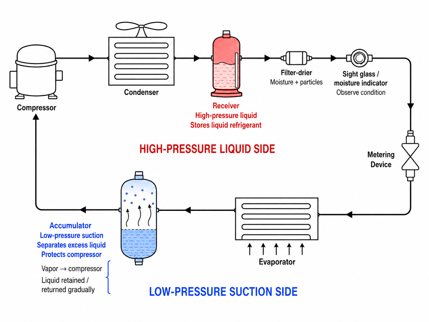
Figure 4.4.1 – Receiver and suction-accumulator locations in the vapor-compression refrigeration cycle.
AI-generated instructional figure: It may contain visual inaccuracies. Use the accompanying lesson text and cited authoritative sources to verify technical and regulatory details.
EPA 608 Exam Focus
What Students Must Remember
- Receiver:
- High side.
- After condenser.
- Before metering device.
- Stores/manages liquid refrigerant.
- Accumulator:
- Low side.
- After evaporator.
- Before compressor.
- Helps protect compressor from liquid refrigerant return.
- Receiver and accumulator are not interchangeable.
- Receiver does not meter refrigerant into the evaporator.
- Accumulator does not replace the metering device.
- A compressor is designed primarily to receive vapor.
- Excess liquid return can cause slugging and lubrication problems.
- A filter-drier:
- Filters solid contaminants.
- Removes moisture.
- Has limited moisture capacity.
- A filter-drier does not remove air or nitrogen.
- A liquid-line filter-drier commonly protects the metering device.
- A suction-line filter-drier can be used for specific cleanup procedures.
- A sight glass allows visual observation of refrigerant condition at its location.
- Sight-glass bubbles do not automatically prove undercharge.
- A clear sight glass does not automatically prove correct charge.
- A moisture indicator indicates moisture condition; it does not remove moisture.
- Moisture-indicator colors are manufacturer specific.
- Filter-drier and deep evacuation perform different jobs.
High-Priority Comparison Table
| Exam Clue | Correct Component / Concept |
|---|---|
| After condenser, stores liquid | Receiver |
| Before metering device, liquid storage | Receiver |
| After evaporator, before compressor | Accumulator |
| Protects compressor from liquid return | Accumulator |
| Removes moisture and particles | Filter-drier |
| Indicates moisture condition | Moisture indicator |
| Visual liquid-line observation | Sight glass |
| Removes air and water vapor during service | Evacuation, not filter-drier |
| Bubbles visible | Requires diagnosis; not automatic proof of undercharge |
| Clear sight glass | Does not by itself prove correct charge |
Typical Exam Question Patterns
Students may be asked to:
- Identify where a receiver is installed.
- State the primary function of a receiver.
- Identify where an accumulator is installed.
- Explain why an accumulator protects the compressor.
- Distinguish a receiver from an accumulator.
- Identify which component stores high-pressure liquid.
- Identify which component separates liquid from suction vapor.
- State the purpose of a filter-drier.
- Recognize that a filter-drier does not remove noncondensables.
- State the purpose of a sight glass.
- State the purpose of a moisture indicator.
- Reject sight-glass bubbles as a universal charging rule.
Common Mistakes and Confusing Points
Mistake 1: Confusing Receiver and Accumulator
Correct distinction:
Receiver
= high side
= liquid storage

Accumulator
= low side
= compressor protection
Mistake 2: Placing the Receiver After the Evaporator
The receiver is normally on the liquid side after the condenser.
Mistake 3: Placing the Accumulator Before the Metering Device
The accumulator is normally after the evaporator and before the compressor.
Mistake 4: Saying the Receiver Protects the Compressor From Liquid Slugging
That is the main role of the suction accumulator, not the receiver.
Mistake 5: Saying the Accumulator Meters Refrigerant Into the Evaporator
The metering device controls refrigerant entering the evaporator.
The accumulator is downstream of the evaporator.
Mistake 6: Thinking the Accumulator Permanently Stores All Liquid
Accumulator design normally provides controlled refrigerant and oil return.
Mistake 7: Thinking a Filter-Drier Removes Air
A filter-drier removes moisture and particles.
Evacuation removes air and other noncondensables.
Mistake 8: Treating the Sight Glass as a Complete Charging Test
Bubbles or a clear glass must be interpreted in the context of the system design and approved charging procedure.
Mistake 9: Treating the Moisture Indicator as a Dryer
It indicates moisture condition.
It does not remove moisture.
Mistake 10: Memorizing One Sight-Glass Moisture Color for Every Product
Use the manufacturer’s legend.
Concept-Check Questions
Question 1
Where is a liquid receiver normally located in a basic refrigeration system that uses one?
A. Between the evaporator and compressor on the suction line
B. Between the compressor and condenser on the discharge line
C. After the condenser and before the metering device on the high-pressure liquid side
D. Downstream of the metering device at the evaporator inlet
Question 2
What is the primary function of a liquid receiver?
A. Store and manage high-pressure liquid refrigerant for the downstream liquid circuit
B. Compress low-pressure vapor
C. Separate liquid from suction vapor immediately before the compressor
D. Remove all air and noncondensables from the system
Question 3
Where is a suction accumulator normally located?
A. Between the condenser and receiver
B. Between the evaporator outlet and compressor inlet
C. Between the compressor discharge and condenser inlet
D. Immediately upstream of the metering device on the high side
Question 4
What is the primary reason for installing a suction accumulator?
A. To raise condenser pressure
B. To meter high-pressure liquid into the evaporator
C. To remove all system moisture
D. To separate excess liquid from suction vapor and help protect the compressor from liquid return
Question 5
What are the two primary functions of a filter-drier?
A. Increase refrigerant pressure and lower refrigerant temperature
B. Filter solid contamination and remove moisture
C. Store refrigerant and meter flow
D. Separate suction liquid and compress vapor
Question 6
Which statement about a moisture-indicating sight glass is correct?
A. It removes moisture from the refrigerant as the refrigerant passes through it.
B. One universal indicator color applies to every refrigerant and every manufacturer.
C. It can indicate moisture condition, but the manufacturer’s legend must be used and the indicator itself does not dry the system.
D. It removes air and nitrogen during system operation.
Question 7
A technician observes bubbles in a liquid-line sight glass. Which conclusion is most appropriate?
A. The system is definitely undercharged and refrigerant must be added immediately.
B. The bubbles require further diagnosis because several operating conditions can produce flashing or bubbles.
C. The compressor is definitely receiving liquid refrigerant.
D. The filter-drier is definitely saturated with moisture.
Question 8
Which statement correctly compares a receiver and an accumulator?
A. Both are installed in the same location and perform the same function.
B. The receiver is a low-side compressor-protection device, while the accumulator is a high-side liquid-storage device.
C. Both components meter refrigerant into the evaporator.
D. The receiver is normally a high-side liquid-storage component, while the accumulator is normally a low-side compressor-protection component.
Answers and detailed explanations will be provided in
4.11 - Answers and Explanations.md.
Section Summary
A receiver, accumulator, filter-drier, and sight glass perform different jobs in the refrigeration circuit.
The receiver is normally:
After condenser
→ High-pressure liquid side
→ Before metering device
Its main function is:
Store / manage liquid refrigerant
The accumulator is normally:
After evaporator
→ Low-pressure suction side
→ Before compressor
Its main function is:
Separate excess liquid from suction vapor
→ protect compressor
The filter-drier:
Filters particles
+
removes moisture
The sight glass and moisture indicator provide information:
Sight glass
→ observe refrigerant condition

Moisture indicator
→ indicate moisture condition
Remember:
- Receiver and accumulator are not interchangeable.
- Accumulator protection does not eliminate the need to correct abnormal floodback.
- Filter-driers have limited moisture capacity.
- Filter-driers do not remove air or nitrogen.
- Evacuation and filter-drying are complementary processes.
- Sight-glass bubbles do not automatically prove undercharge.
- A clear sight glass does not automatically prove correct charge.
- Moisture-indicator colors must be interpreted using the manufacturer’s legend.
The next section introduces the manifold gauge set and service hoses used to connect instruments and service equipment to the refrigeration circuit.
See Section 4.5 - Manifold Gauge Set and Service Hoses.
References
Project Source
- Current EPA Section 608 teaching-material project outline, Module 4 — Refrigeration Cycle Components Gauges and Pressure-Temperature Relationships, Section 4.4. Required scope: receiver location and function, accumulator location and function, liquid protection of compressor, metering-device relationship, filter-drier purpose, moisture indicators and sight glasses, and Figure 4.4.1.
EPA 608 Teaching Reference
- International Training Institute for the Sheet Metal and Air Conditioning Industry, EPA Section 608 Study Guide, recovery and refrigeration-system service material. The guide discusses receivers/storage tanks in refrigerant service and filter use in recovery/recycling equipment and supports the broader refrigerant-management context for liquid storage and contamination control.
HVAC Technical References
-
Justin Kauwale, Mechanical PE: HVAC & Refrigeration Textbook, 2025 ed., Refrigeration Distribution & Systems section. The text places an accumulator on the suction side after the evaporator for compressor liquid protection; places a receiver after the condenser for liquid collection/storage; describes liquid-line filter/dryer function; and discusses sight-glass use near the expansion device.
-
Rex Miller and Mark R. Miller, HVAC Licensing Study Guide, 3rd ed., refrigeration servicing material. The text locates a filter-drier in the liquid line at the condenser outlet and describes its screens and desiccant as filtering foreign particles and absorbing moisture.
-
Edward G. Pita, Air Conditioning Principles and Systems: An Energy Approach, 4th ed., Chapter 13, vapor-compression refrigeration system and equipment concepts used to place auxiliary components within the basic refrigeration circuit.
-
NCEES, PE Mechanical Reference Handbook, Version 2.0, refrigeration-system material used as a supplemental engineering reference for refrigeration components and system arrangements.